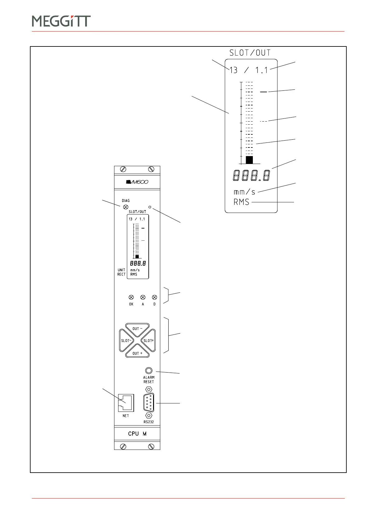
Output signal
(for example,
Channel 1,
Output 1)
Danger threshold
Alert threshold
Bargraph
(51 segments)
Digital display
Measurement
unit
Rectifier
function
Slot (module number)
Enlarged view of display
Green diagnostic LED:
* Off – CPUM is off or
starting
* Green – Normal operation
(CPUM running correctly)
and access to the CPUM
card is allowed
* Green blinking slowly –
Normal operation
(CPUM running correctly)
and access to the CPUM
card is restricted
* Green blinking quickly for
five seconds – CPUM is
resetting to its default
VM600 MPS rack
(CPUM) security settings.
See Table 6-1.
Potentiometer to adjust
display contrast
Status LEDs:
OK line check (green)
Alert (yellow)
Danger (red),
These three LEDs indicate the status of either:
the displayed slot/output or
the entire rack (when slot = 0).
Keys to select the signal to be displayed.
Use SLOT and SLOT+ to select the slot (module) and
OUT and OUT+ to run through the available signals.
These keys are also used to help configure the
VM600 MPS rack (CPUM) security settings.
Push-button to reset all latched alarms (and associated
relays) for MPC4 and AMC8 cards in the rack
‘RS232’ connector (D-sub (DE-09)) for primary serial
connection, used for VM600 rack configuration and
communications
‘NET’ connector
(8P8C (RJ45)) for primary
Ethernet connection,
used for VM600 rack
configuration and
communications,
and Modbus TCP
communications
Figure 2-11: Elements on the CPUM
 Loading...


