ZS3 Service Manual Page 230 of 295
2. To remove the display cable from the netted stretch shielding through which it is
routed (with other system cables) slide the netted stretch shielding together down
its length, to cause the shielding to expand in diameter sufficiently to slide the Main
Board end connectors out of the shielding.
3. Pay special attention to the routing (looping) and retention (cable tie) of the display
cable, within the upper area of the main column of the system, in order to
reproduce this layout during re-assembly.
Display Removal:
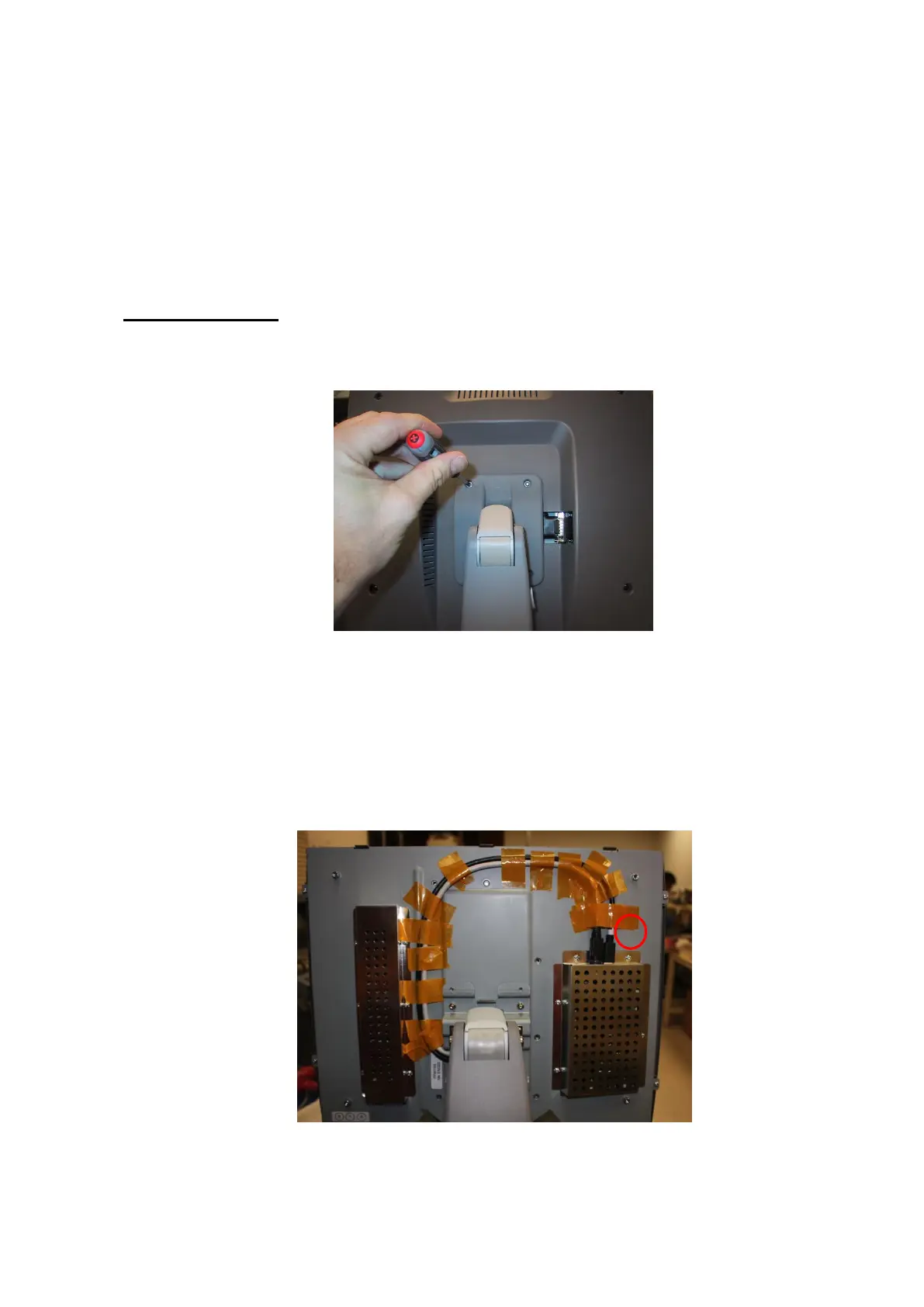
1. Remove the four (4) Phillips-head screws that are retaining the plastic display
hinge back cover, and remove cover and insert.
Figure 19.15-ZS3
2. Remove the (6) Phillips-head screws that are retaining the plastic display hinge
back cover, and remove cover and insert.
3. Remove the tape securing the video cable to the display.
4. Grasp the connector housing and slide back to unlatch the cable from the video
board.
Figure 19.16-ZS3
 Loading...