EasyManua.ls Logo

Mitsubishi L Series User Manual

Mitsubishi L Series
244 pages
To Next Page IconTo Next Page
To Previous Page IconTo Previous Page
Page #111 background imageLoading...
Page #111 background image
109
CHAPTER 8 FUNCTIONS
8
8.14 Logging Function
(10)When checking logging data without stopping logging
Logging data can be checked during logging. Logging data can be easily checked on a display device just by
monitoring the buffer memory without stopping logging on the display device.
To check the logging data, adjust the logging cycle to prevent the logging data from being updated during read.
(a) Checking method
Read the logging data monitoring the storage locations of the latest data and of the oldest data in the following
buffer memory areas.
(b) Precautions
•Set CH Logging cycle setting value (Un\G1032 to Un\G1035) to the cycle that confirmation and read of
data surely complete before logging data is updated. If the logging cycle is short, logging data may be
updated while confirming and reading data.
After acquiring the logging data which need to be checked, monitor the variation of the head pointer and
the number of logging data. Acquire logging data after the stored value changes.
If the update of the data and the data being checked do not synchronize due to the relationship between
the logging cycle and the scan time of the CPU module, adjust the logging cycle.
To check the data without paying attention to logging cycle, use the logging hold.
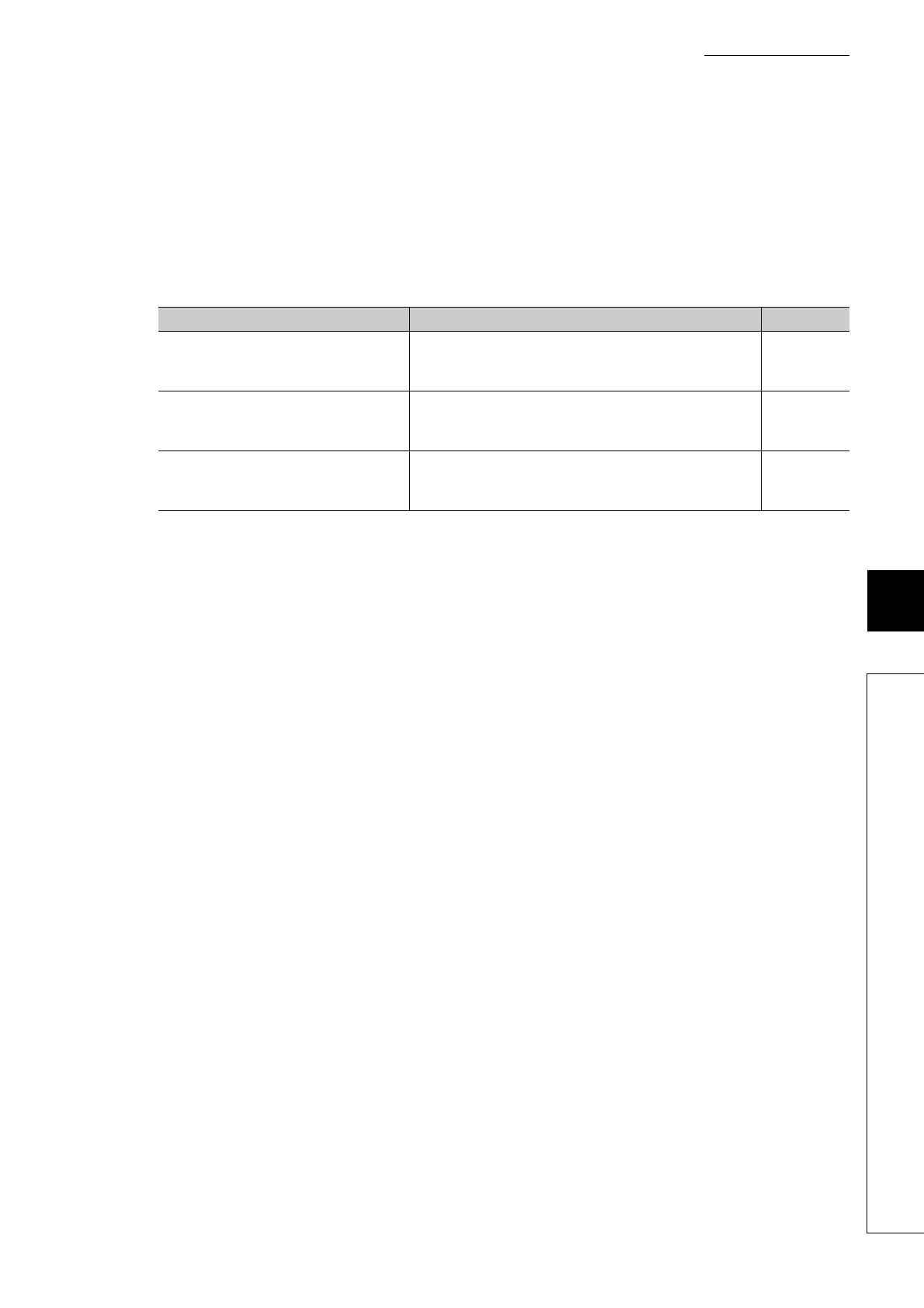
Buffer memory Description Reference
CH Head pointer (Un\G1090 to
Un\G1093)
The buffer memory where the oldest data is stored can be
checked by number starting from the start address in the
logging data storage area.
Page 195,
Appendix
2(40)
CH Latest pointer (Un\G1098 to
Un\G1101)
The buffer memory where the latest data is stored can be
checked by number starting from the start address in the
logging data storage area.
Page 195,
Appendix
2(41)
CH Number of logging data (Un\G1106 to
Un\G1109)
The number of data stored in the logging data storage area
can be checked.
Page 196,
Appendix
2(42)

Table of Contents

Other manuals for Mitsubishi L Series

Questions and Answers:

Mitsubishi L Series Specifications

General IconGeneral
BrandMitsubishi
ModelL Series
CategoryEngine
LanguageEnglish

Summary

SAFETY PRECAUTIONS

Design Precautions

Precautions related to system design and module protection, including buffer memory usage.

Installation Precautions

Safety measures for installing the module and system components, covering power supply and module handling.

Wiring Precautions

Safety guidelines for electrical wiring of the module, including grounding and terminal block handling.

Startup and Maintenance Precautions

Safety measures during initial startup and routine maintenance, covering module handling and static discharge.

Disposal Precautions

Guidelines for safe and environmentally responsible product disposal as industrial waste.

CONDITIONS OF USE FOR THE PRODUCT

INTRODUCTION

COMPLIANCE WITH EMC AND LOW VOLTAGE DIRECTIVES

RELEVANT MANUALS

MANUAL PAGE ORGANIZATION

CHAPTER 1 A/D CONVERTER MODULE

Application

Describes how the A/D converter module is used in practical applications for converting analog signals.

Features

Highlights the key characteristics and capabilities of the A/D converter module, such as high-speed conversion.

CHAPTER 2 PART NAMES

CHAPTER 3 SPECIFICATIONS

General Specifications

Provides fundamental technical specifications for the A/D converter module, referring to safety guidelines.

Performance Specifications

Details the operational performance metrics like input points, ranges, accuracy, and conversion speed.

Function List

Lists all available functions of the A/D converter module with references to their respective sections.

I/O Signal List

Details the input and output signals used by the A/D converter module, including device numbers and signal names.

List of Buffer Memory Addresses

Maps buffer memory addresses to their functions, default values, and read/write capabilities.

CHAPTER 4 PROCEDURES BEFORE STARTING THE OPERATION

CHAPTER 5 SYSTEM CONFIGURATION

Overall System Configuration

Illustrates typical system configurations for integrating the A/D converter module with CPU or head modules.

Applicable System

Specifies compatible systems and software versions for the A/D converter module.

Restrictions When A/D Converter Module is Connected to Head Module

Details limitations, such as the non-usability of dedicated instructions, when connecting to a head module.

CHAPTER 6 INSTALLATION AND WIRING

Installation Environment and Installation Position

Guidelines for selecting an appropriate installation environment and location for the module.

Terminal Block

Describes the terminal block, including precautions, signal names, and removal/installation procedures.

Wiring

Provides wiring diagrams for voltage and current inputs to the module's terminal block.

External Wiring

Details the external wiring connections for voltage and current inputs, including shielding and unused channels.

CHAPTER 7 VARIOUS SETTINGS

Addition of Modules

Explains how to add the A/D converter module model name to the project configuration.

Switch Setting

Covers setting the input range and operation mode for each channel using the 'Switch Setting' dialog.

Parameter Setting

Details how to configure various parameters for each channel via the 'Parameter' dialog.

Auto Refresh

Describes the function for automatically transferring buffer data to specified devices.

Offset/Gain Setting

Explains how to configure offset and gain settings for user range using GX Works2 or a program.

CHAPTER 8 FUNCTIONS

Processing Each Function

Explains the processing order and types of digital output values, including scaling and minimum/maximum values.

A/D Conversion Methods

Details methods for sampling or averaging analog input values, including time, count, and moving averages.

Input Signal Handling

Covers extended input ranges, error detection, and extension functions for analog input signals.

Output and Monitoring Functions

Covers warning output, scaling, shift, digital clipping, and difference conversion functions for output values.

Data Logging and Integration

Covers collecting, storing data, and integrating flow amounts, including trigger conditions and cycle settings.

Error Handling and Management

Covers error logging, module error collection, and procedures for clearing errors and alarms.

Saving and Restoring Offset/Gain Values

Allows saving and restoring offset/gain values for user range settings, including methods and procedures.

CHAPTER 9 DISPLAY UNIT

Display Unit

Describes the LCD display unit for checking system status and error information.

Menu Transition

Illustrates the organization and navigation of the display unit's menus for module settings.

List of Setting Value Change Screens

Provides a list of screens for changing module settings via the display unit interface.

CHAPTER 10 PROGRAMMING

Procedure for Programming

Outlines the steps for creating programs for A/D conversion, including initial and auxiliary programs.

When Using the Module in a Standard System Configuration

Shows program examples for standard system configurations, including system setup and programming conditions.

When A/D Converter Module is Connected to Head Module

Describes system configuration and programming for head module connections, including initial settings.

CHAPTER 11 TROUBLESHOOTING

Checking on the Module Detailed Information

Guides on how to check module errors and status through detailed information in the system monitor.

Checking by Latest Error Code (Un\G19)

Explains how to check error codes and alarm codes using the Latest Error Code buffer memory.

Checking on the Module Error Collection Function

Describes checking module errors stored by the error collection function in the CPU module.

Error Code List

Provides a comprehensive list of error codes, their causes, and recommended actions.

Alarm Code List

Lists alarm codes, their causes, and corresponding actions for process and input signal errors.

Troubleshooting

Offers solutions for common operational issues based on LED status (RUN, ERR, ALM).

Checking the Status of the A/D Converter Module by the System Monitor

Details how to check module LED status and switch settings via the system monitor in GX Works2.

APPENDICES

Appendix 1 Details of I/O Signals

Details the A/D converter module's input and output signals, including flags and requests.

Appendix 2 Details of Buffer Memory Addresses

Provides a comprehensive list of buffer memory addresses, their functions, and default values.

Appendix 3 I/O Conversion Characteristic of A/D Conversion

Explains the conversion characteristics between analog input and digital output, including offset and gain values.

Appendix 5 Dedicated Instruction

Lists and describes dedicated instructions for the A/D converter module, such as G(P).OFFGAN.

Appendix 9 When Using GX Developer or GX Configurator-AD

Describes operating procedures using GX Developer and GX Configurator-AD for module parameter settings.

REVISIONS

WARRANTY

Related product manuals