132
(b) Trace Count Setting
• Total Count: The number of times that data are stored in the memory
• Count Before Trigger: The number of data storages to retain before the trigger
• Count After Trigger: A value obtained by "the Count Before Trigger value subtracted from the Total Count
value.
(c) Data Acquisition Timing Setting
Set the timing for collecting trace data.
*1 Pay attention to the sampling interval and sampling processing time for one sampling since the sampling trace is
performed as interrupt processing. If the sampling processing time for one sampling is long, "WDT ERROR" may occur.
*2 Data are collected when the status immediately before execution of the specified step changes to the specified status.
(d) Trigger Condition Setting
Select the trigger point.
*1 Trigger point is the timing when the status immediately before execution of the specified step changes to the specified
status.
Item Description
Each Scan Collects trace data during END processing of each scan.
Specified Interval
*1
Collects trace data at specified time intervals.
Detail Setting
Specify a device or label from the following.
• Bit device: X (DX), Y (DY), M, L, F, SM, V, B, SB, T (contact), ST (contact), C (contact), FX, FY, BL\S
• Word device: T (current value), ST (current value), C (current value), D, D (extended data register), SD, W,
W (extended link register), SW, R, Z, ZR, FD, U\G
The following modifications are available for the above devices.
• Digit specification of bit device
• Bit specification of word device
• Indirect specification of word device
• Index modification
• Step No. specification
*2
When the set conditions are met, data collection is performed.
Item Description
At the Time of Trace
Instruction Execution
The time of execution of the TRACE instruction is set as a trigger.
At the Time of Manual Trigger
Execution
Trigger ExecutionThe time of execution of the trigger from the programming tool is set as a trigger.
Detail Setting
Specify a device or label from the following.
• Bit device: X (DX), Y (DY), M, L, F, SM, V, B, SB, T (contact), ST (contact), C (contact), FX, FY
• Word device: T (current value), ST (current value), C (current value), D, D (extended data register), SD, W,
W (extended link register), SW, R, ZR
The following modifications are available for the above devices.
• Bit specification of word device
• Step No. specification
*1
When the set conditions are met, this timing is set as a trigger point.
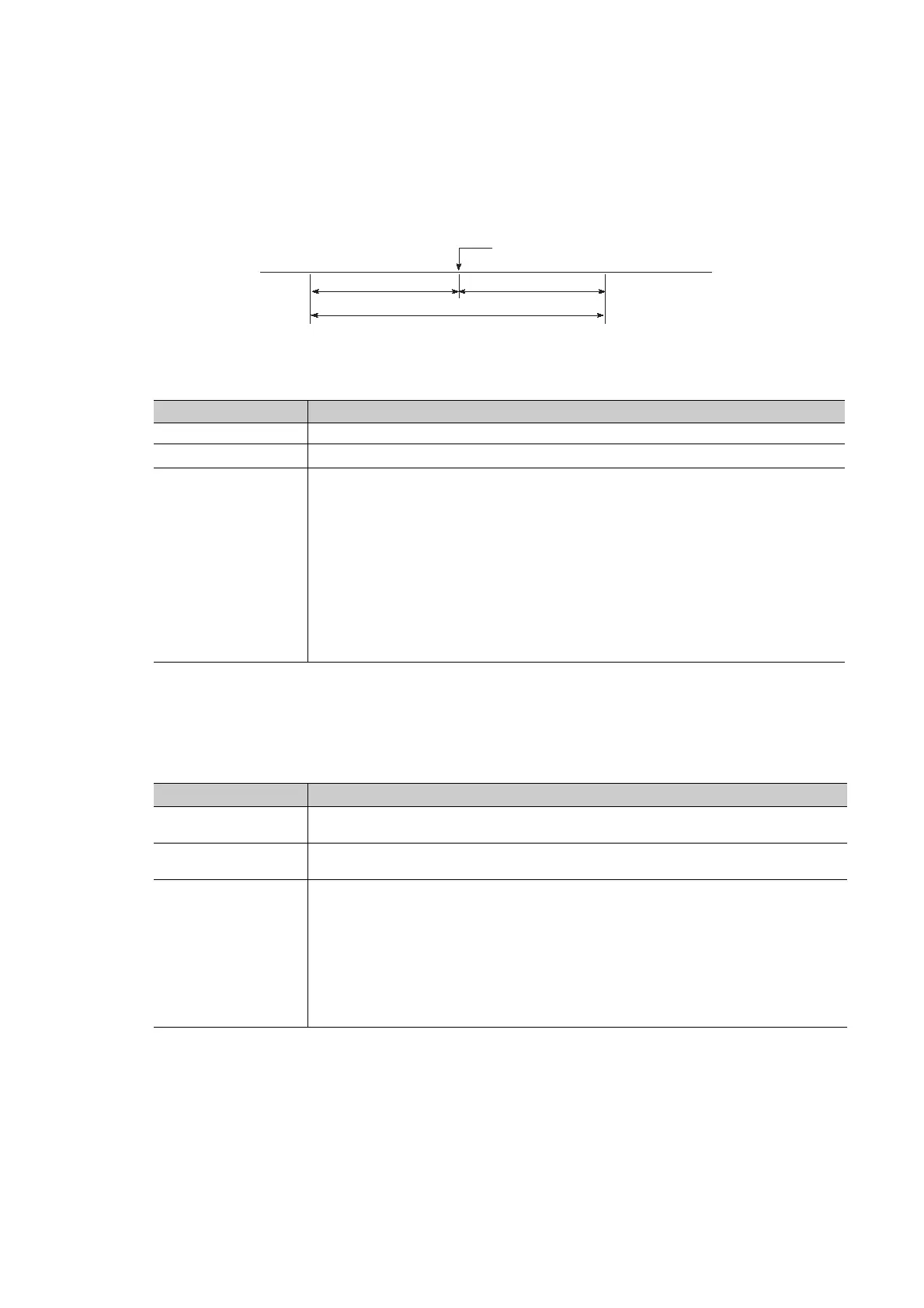
Trigger point
Count after trigger
Count before trigger
Total count
Trace
 Loading...