EasyManua.ls Logo

Mitsubishi L02CPU User Manual

Mitsubishi L02CPU
340 pages
To Next Page IconTo Next Page
To Previous Page IconTo Previous Page
Page #275 background imageLoading...
Page #275 background image
273
CHAPTER 5 DEVICES
5
5.10 Interrupt Pointer (I)
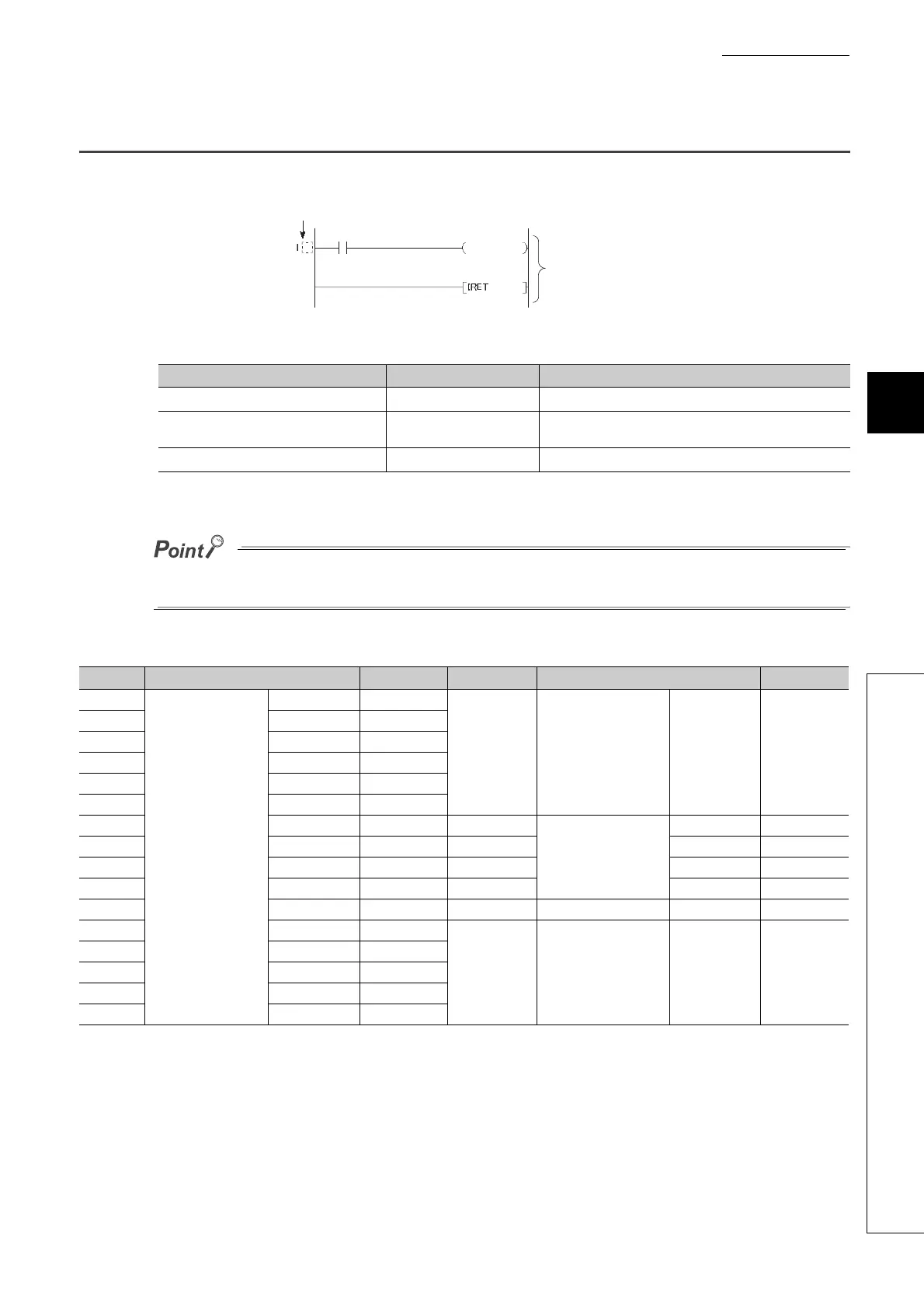
The interrupt pointer (I) is used as a label at the start of an interrupt program, and can be used in any programs.
The number of points available for the interrupt pointer is 256 (I0 to I255). The following shows interrupt factors for the
applicable interrupt pointers.
*1 Interrupt pointer numbers can be changed in the PLC Parameter dialog box.
*2 They can be used for interruptions by built-in I/O by configuring parameter in the "PLC Parameter" dialog box.
To use the intelligent function module interrupt, set values in the "Interrupt Pointer Setting" dialog box opened from the "PLC
System" tab of the PLC Parameter dialog box.
The list of interrupt pointer numbers and interrupt factors are shown below.
*1 The time-limit value of the internal timer is set by default. In the PLC System tab of the PLC Parameter dialog box, the
value can be changed within the range of 2ms to 1000ms in increments of 1ms.
*2 When an interrupt occurs, even if no interrupt pointer exists on the program, "CAN'T EXECUTE(I)" (error code: 4220)
does not occur.
*3 Among I50 to I255, I50 has the highest priority (priority 21), and I255 has the lowest priority (priority 226).
Interrupt factor Interrupt pointer No. Description
Interrupt by built-in I/O
I0 to I15
*1
Interrupt from a built-in I/O
Interrupt by an internal timer I28 to I31
Interrupt at fixed intervals by an internal timer of the CPU
module
Intelligent function module interrupt
I50 to I255
*2
Interrupt from the intelligent function module
I No. Interrupt factor Priority I No. Interrupt factor Priority
I0
Interrupt by
built-in I/O
1st point 5
I16 to I27 ⎯ Empty ⎯
I1 2nd point 6
I2 3rd point 7
I3 4th point 8
I4 5th point 9
I5 6th point 10
I6 7th point 11 I28
Interrupt by internal
timer
*1 *2
100ms 4
I7 8th point 12 I29 40ms 3
I8 9th point 13 I30 20ms 2
I9 10th point 14 I31 10ms 1
I10 11th point 15 I32 to I49 ⎯ Empty ⎯
I11 12th point 16
I50 to I255
Intelligent function
module interrupt
Empty
21 to 226
*3
I12 13th point 17
I13 14th point 18
I14 15th point 19
I15 16th point 20
Interrupt pointer (interrupt program label)
Interrupt program

Table of Contents

Question and Answer IconNeed help?

Do you have a question about the Mitsubishi L02CPU and is the answer not in the manual?

Mitsubishi L02CPU Specifications

General IconGeneral
BrandMitsubishi
ModelL02CPU
CategoryController
LanguageEnglish

Summary

MITSUBISHI MELSEC-L CPU Module User's Manual

SAFETY PRECAUTIONS

Design Precautions

Essential safety guidelines for designing systems with the controller, covering circuits and operations.

Installation Precautions

Crucial steps for safely installing the programmable controller modules, including environment and interconnection.

Wiring Precautions

Important safety measures for correctly wiring the controller, covering grounding, terminals, and cable routing.

Startup and Maintenance Precautions

Precautions for safe startup, operation, and maintenance procedures, including handling batteries and static electricity.

PART 1 PROGRAMMING

CHAPTER 1 BASIC PROCEDURE FOR PROGRAMMING

Guides through the fundamental steps of PLC programming.

CHAPTER 1 BASIC PROCEDURE FOR PROGRAMMING

1.3 Creating a Program

Explains the fundamental steps and prerequisites for program creation.

1.5 Writing a Project to the CPU Module

Describes how to transfer the project, including memory formatting.

1.6 Checking an Operation of the CPU Module

Outlines procedures for verifying the CPU module's operation after programming.

CHAPTER 3 CPU MODULE FUNCTIONS

3.3 Watchdog Timer (WDT)

Details the watchdog timer for detecting hardware failures and program errors.

3.11 File Password 32

Explains how to protect files stored in the CPU module with passwords.

3.13 Remote Operation

Details methods for controlling CPU module operations remotely.

3.21 Writing Programs in RUN Status

Describes online program changes while the CPU module is running.

3.23 Self-Diagnostic Function

Covers the CPU module's self-diagnostic capabilities for error detection.

3.24 Error Clear

Explains how to clear detected continuation errors by type.

3.30 CPU Module Change Function with SD Memory Card

Explains data backup and restoration using an SD memory card for module replacement.

Appendix 1 Parameter Setting

Appendix 1.2 PLC Parameter

Details various PLC parameter settings including name, system, file, RAS, boot, and program.

Appendix 1.4 Remote Password setting

Provides screens and details for setting remote passwords for access control.

Appendix 1.2 PLC Parameter

2. PLC System Setting

Configures system-level parameters for CPU module operation.

4. PLC RAS Setting

Configures Reliability, Availability, and Serviceability (RAS) functions.

9. I/O Assignment Setting

Configures the connecting status and assignments of modules in the system.

Related product manuals