329
APPEN
DIX
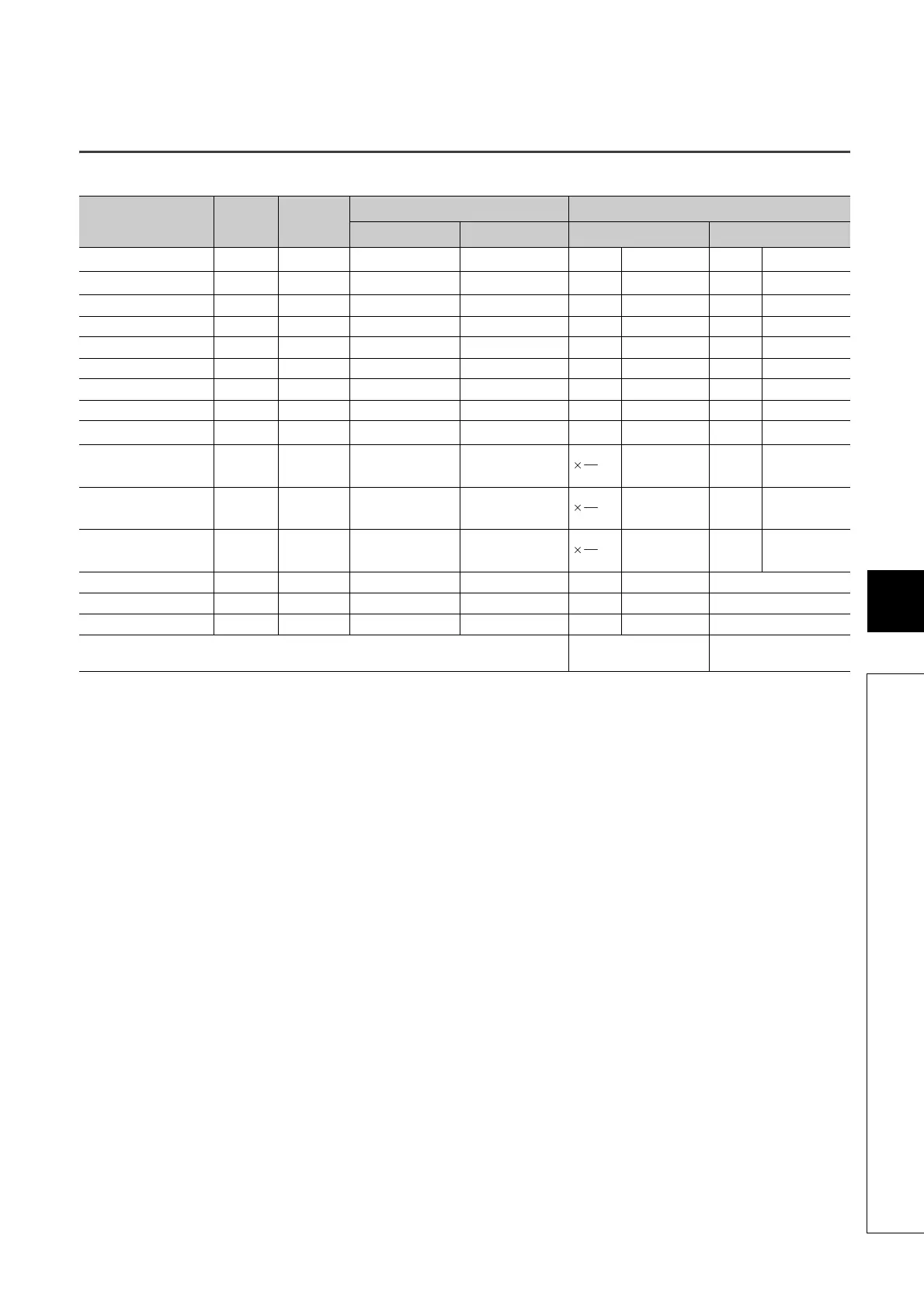
Appendix 8 Device Point Assignment Sheet
Appendix 8 Device Point Assignment Sheet
*1 The points are fixed for the system. (Cannot be changed) The points for the step relay (S) can be changed to 0.
*2 Up to 32K points can be set for each device. (60K for the internal relay and link relay.)
*3 Enter the values multiplied (or divided) by the number shown in the Size (words) column.
Device name Symbol
Numeric
notation
Number of device points
*2
Restriction check
Points Range
Size (words)
*3
Points (bits)
*2
Input relay
*1
X 16 8K (8192) X0000 to X1FFF /16 512 ×1 8192
Output relay
*1
Y 16 8K (8192) Y0000 to Y1FFF /16 512 ×1 8192
Internal relay M 10 K ( ) M0 to /16 ×1
Latch relay L 10 K ( ) L0 to /16 ×1
Link relay B 16 K ( ) B0000 to /16 ×1
Annunciator F 10 K ( ) F0 to /16 ×1
Link special relay SB 16 K ( ) SB0000 to /16 ×1
Edge relay V 10 K ( ) V0 to /16 ×1
Step relay
*1
S 10 8K (8192) S0 to S8191 /16 512 ×1
Timer T 10 K ( ) T0 to ×2
Retentive timer ST 10 K ( ) ST0 to ×2
Counter C 10 K ( ) C0 to ×2
Data register D 10 K ( ) D0 to ×1 -
Link register W 16 K ( ) W0000 to ×1 -
Link special register SW 16 K ( ) SW0000 to ×1 -
Tota l
(29696 or less)
18
16
18
16
18
16