EasyManua.ls Logo

Mitsubishi L02CPU User Manual

Mitsubishi L02CPU
340 pages
To Next Page IconTo Next Page
To Previous Page IconTo Previous Page
Page #257 background imageLoading...
Page #257 background image
255
CHAPTER 5 DEVICES
5
5.5 Index Register/Standard Device Register (Z)
5.5.1 Index Register (Z)
5.5 Index Register/Standard Device Register (Z)
5.5.1 Index Register (Z)
The index register is used for indirect specification (index modification) in programs. Index modification uses one point
of the index register.
The index register has 20 points (Z0 to Z19).
(1) Bit structure of the index register
One point of the index register consists of 16 bits, and data can be read or written in units of 16 bits.
Link register data are handled as signed data. In the case of the hexadecimal notation, 0000
H
to FFFF
H
can be stored.
However, because the most significant bit represents a sign bit, decimal values that can be specified are -32768 to 32767.
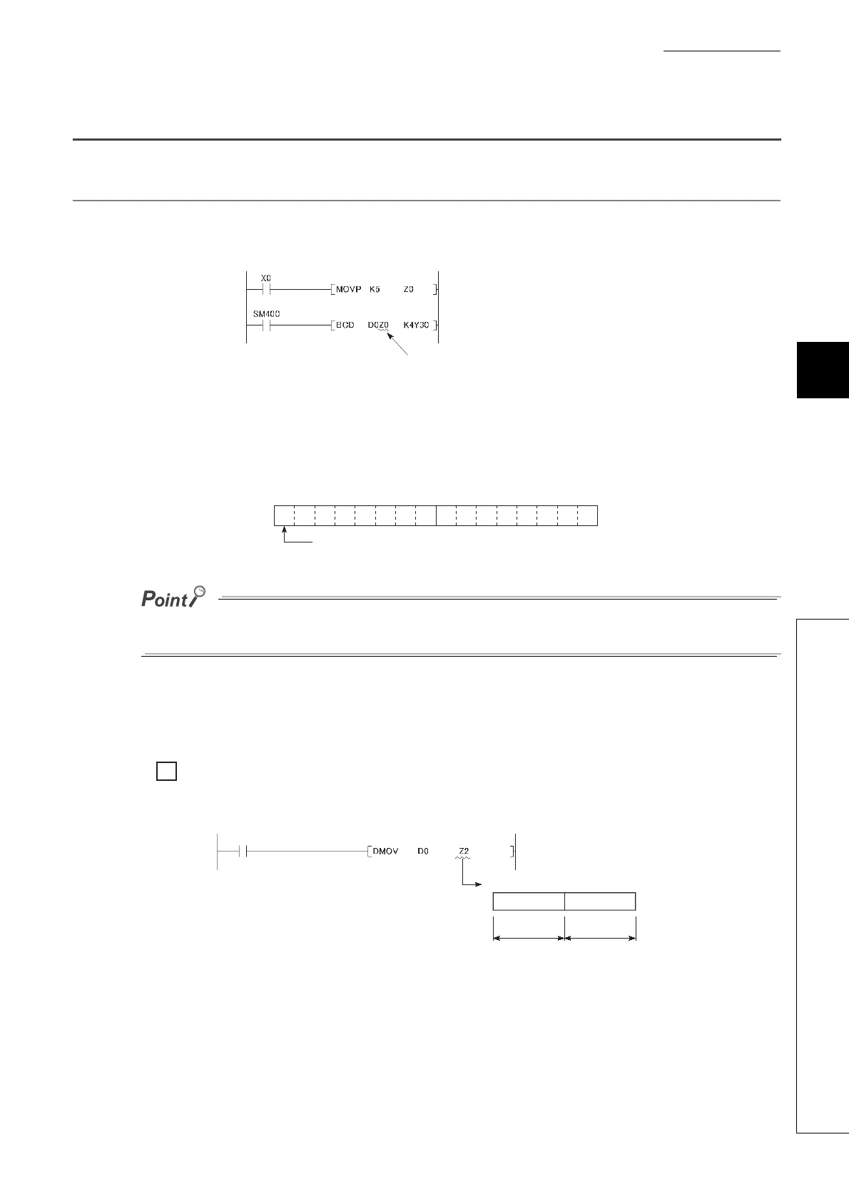
(2) Using in a 32-bit instruction
The processing target is Z
n
and Z
n+1
. The lower 16 bits correspond to the specified index register number (Z
n
),
and the higher 16 bits correspond to the specified index register number + 1.
When Z2 is specified in the DMOV instruction, Z2 represents the lower 16 bits and Z3 represents the
higher 16 bits.
(The most significant bit in a 32-bit structure is a sign bit.)
Specify the index register by one point
(16 bits).
Zn
b15
to
b0
The most significant bit is a sign bit.
Ex.
Ex.
Z3
Lower 16 bits Upper 16 bits
Z2
Processing target: Z2, Z3

Table of Contents

Question and Answer IconNeed help?

Do you have a question about the Mitsubishi L02CPU and is the answer not in the manual?

Mitsubishi L02CPU Specifications

General IconGeneral
BrandMitsubishi
ModelL02CPU
CategoryController
LanguageEnglish

Summary

MITSUBISHI MELSEC-L CPU Module User's Manual

SAFETY PRECAUTIONS

Design Precautions

Essential safety guidelines for designing systems with the controller, covering circuits and operations.

Installation Precautions

Crucial steps for safely installing the programmable controller modules, including environment and interconnection.

Wiring Precautions

Important safety measures for correctly wiring the controller, covering grounding, terminals, and cable routing.

Startup and Maintenance Precautions

Precautions for safe startup, operation, and maintenance procedures, including handling batteries and static electricity.

PART 1 PROGRAMMING

CHAPTER 1 BASIC PROCEDURE FOR PROGRAMMING

Guides through the fundamental steps of PLC programming.

CHAPTER 1 BASIC PROCEDURE FOR PROGRAMMING

1.3 Creating a Program

Explains the fundamental steps and prerequisites for program creation.

1.5 Writing a Project to the CPU Module

Describes how to transfer the project, including memory formatting.

1.6 Checking an Operation of the CPU Module

Outlines procedures for verifying the CPU module's operation after programming.

CHAPTER 3 CPU MODULE FUNCTIONS

3.3 Watchdog Timer (WDT)

Details the watchdog timer for detecting hardware failures and program errors.

3.11 File Password 32

Explains how to protect files stored in the CPU module with passwords.

3.13 Remote Operation

Details methods for controlling CPU module operations remotely.

3.21 Writing Programs in RUN Status

Describes online program changes while the CPU module is running.

3.23 Self-Diagnostic Function

Covers the CPU module's self-diagnostic capabilities for error detection.

3.24 Error Clear

Explains how to clear detected continuation errors by type.

3.30 CPU Module Change Function with SD Memory Card

Explains data backup and restoration using an SD memory card for module replacement.

Appendix 1 Parameter Setting

Appendix 1.2 PLC Parameter

Details various PLC parameter settings including name, system, file, RAS, boot, and program.

Appendix 1.4 Remote Password setting

Provides screens and details for setting remote passwords for access control.

Appendix 1.2 PLC Parameter

2. PLC System Setting

Configures system-level parameters for CPU module operation.

4. PLC RAS Setting

Configures Reliability, Availability, and Serviceability (RAS) functions.

9. I/O Assignment Setting

Configures the connecting status and assignments of modules in the system.

Related product manuals