226
CHAPTER 5 DEVICES
This chapter describes the devices that can be used in the CPU module.
5.1 Device List
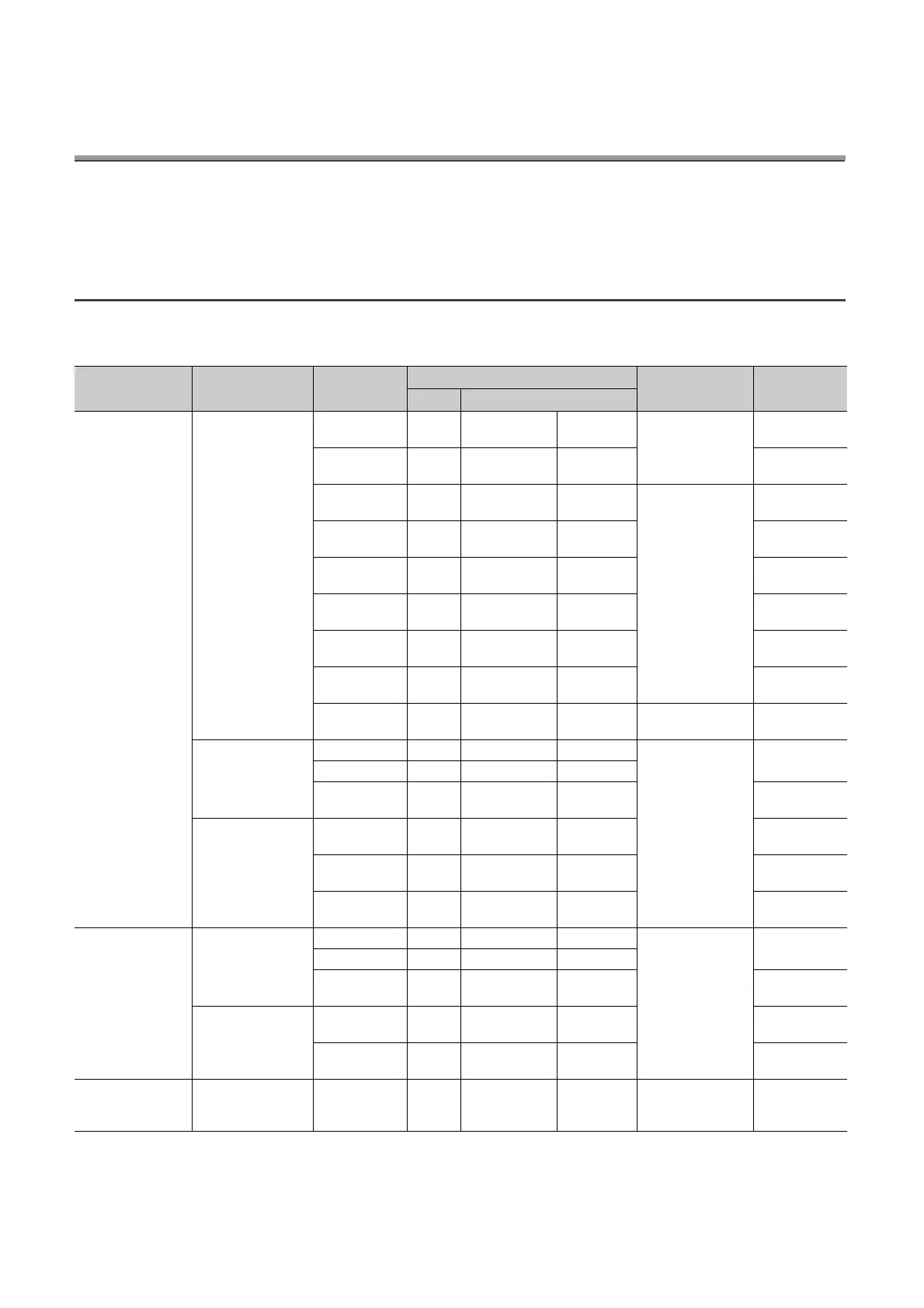
The following table shows the devices used in the CPU module and applicable ranges.
(To the next page)
Classification Type Device name
Default
Parameter-set
range
Reference
Points Range
Internal user device
Bit device
Input 8192 X0 to X1FFF Hexadecimal
Cannot be set
Page 231,
Section 5.2.1
Output 8192 Y0 to Y1FFF Hexadecimal
Page 231,
Section 5.2.2
Internal relay 8192 M0 to M8191 Decimal
Can be set
(Internal user device,
up to 29K words in
total)
Page 232,
Section 5.2.3
Latch relay 8192 L0 to L8191 Decimal
Page 232,
Section 5.2.4
Link relay 8192 B0 to B1FFF Hexadecimal
Page 232,
Section 5.2.5
Annunciator 2048 F0 to F2047 Decimal
Page 233,
Section 5.2.6
Link special
relay
2048 SB0 to SB7FF Hexadecimal
Page 236,
Section 5.2.7
Edge relay 2048 V0 to V2047 Decimal
Page 236,
Section 5.2.8
Step relay 8192 S0 to S8191 Decimal
Select either 0K point
or 8K points.
Page 237,
Section 5.2.9
• Bit device
(contacts and coils)
• Word device
(current value)
Timer 2048 T0 to T2047 Decimal
Can be set
(Internal user device,
up to 29K words in
total)
Page 238,
Section 5.2.10
Retentive timer 0 (ST0 to ST2047) Decimal
Counter 1024 C0 to C1023 Decimal
Page 244,
Section 5.2.11
Word device
Data register 12288 D0 to D12287 Decimal
Page 247,
Section 5.2.12
Link register 8192 W0 to W1FFF Hexadecimal
Page 248,
Section 5.2.13
Link register 2048 SW0 to SW7FF Hexadecimal
Page 249,
Section 5.2.14
Internal system
device
Bit device
Function input 16 FX0 to FXF Hexadecimal
Cannot be set
Page 250,
Section 5.3.1
Function output 16 FY0 to FYF Hexadecimal
Special relay 2048 SM0 to SM2047 Decimal
Page 252,
Section 5.3.2
Word device
Function register 5 FD0 to FD4 Decimal
Page 250,
Section 5.3.1
Special register 2048 SD0 to SD2047 Decimal
Page 252,
Section 5.3.3
Module access
device
Word device
Intelligent
function module
device
65536
Un\G0 to
Un\G65535
*2
Decimal Cannot be set
Page 253,
Section 5.4