EasyManua.ls Logo

Mitsubishi L02CPU User Manual

Mitsubishi L02CPU
340 pages
To Next Page IconTo Next Page
To Previous Page IconTo Previous Page
Page #235 background imageLoading...
Page #235 background image
233
CHAPTER 5 DEVICES
5
5.2 Internal User Devices
5.2.6 Annunciator (F)
The annunciator (F) is an internal relay which can be effectively used in fault detection programs for user-created
system. Whenever an annunciator is turned on, SM62 turns on and the anuunciator number is stored in SD62 to
SD79. By monitoring SD62 to SD79, the system can be checked for error and failure.
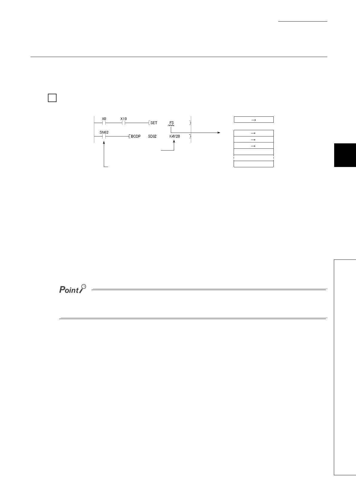
When F5 is turned on, the corresponding annunciator number is output to the outside.
(1) Turning on the annunciator
Use either of the following instructions.
(a) SET F instruction
Annunciator turns on only on the leading edge of an input condition. Even if the input condition turns off, the
annunciator is held on. Using many annunciator numbers can shorten scan time more than using the OUT F
instruction.
(b) OUT F instruction
Since the processing is performed for every scan, the scan time is longer than the case of using the SET F
instruction.
If the annunciator is turned on with any instruction other than SET F and OUT F (for example, the MOV instruction), the
same operation as the internal relay (M) is performed. The ON information is not stored in SM62, and annunciator numbers
are not stored in SD62 and SD64 to SD79.
Ex.
Ex.
SM62
SD62
SD63
SD64
SD65
SD79
0
0
[Fault detection program]
Outputs number of
the annunciator that turned on.
Annunciator ON detection
OFF ON
0 5
0 1
0 5

Table of Contents

Question and Answer IconNeed help?

Do you have a question about the Mitsubishi L02CPU and is the answer not in the manual?

Mitsubishi L02CPU Specifications

General IconGeneral
BrandMitsubishi
ModelL02CPU
CategoryController
LanguageEnglish

Summary

MITSUBISHI MELSEC-L CPU Module User's Manual

SAFETY PRECAUTIONS

Design Precautions

Essential safety guidelines for designing systems with the controller, covering circuits and operations.

Installation Precautions

Crucial steps for safely installing the programmable controller modules, including environment and interconnection.

Wiring Precautions

Important safety measures for correctly wiring the controller, covering grounding, terminals, and cable routing.

Startup and Maintenance Precautions

Precautions for safe startup, operation, and maintenance procedures, including handling batteries and static electricity.

PART 1 PROGRAMMING

CHAPTER 1 BASIC PROCEDURE FOR PROGRAMMING

Guides through the fundamental steps of PLC programming.

CHAPTER 1 BASIC PROCEDURE FOR PROGRAMMING

1.3 Creating a Program

Explains the fundamental steps and prerequisites for program creation.

1.5 Writing a Project to the CPU Module

Describes how to transfer the project, including memory formatting.

1.6 Checking an Operation of the CPU Module

Outlines procedures for verifying the CPU module's operation after programming.

CHAPTER 3 CPU MODULE FUNCTIONS

3.3 Watchdog Timer (WDT)

Details the watchdog timer for detecting hardware failures and program errors.

3.11 File Password 32

Explains how to protect files stored in the CPU module with passwords.

3.13 Remote Operation

Details methods for controlling CPU module operations remotely.

3.21 Writing Programs in RUN Status

Describes online program changes while the CPU module is running.

3.23 Self-Diagnostic Function

Covers the CPU module's self-diagnostic capabilities for error detection.

3.24 Error Clear

Explains how to clear detected continuation errors by type.

3.30 CPU Module Change Function with SD Memory Card

Explains data backup and restoration using an SD memory card for module replacement.

Appendix 1 Parameter Setting

Appendix 1.2 PLC Parameter

Details various PLC parameter settings including name, system, file, RAS, boot, and program.

Appendix 1.4 Remote Password setting

Provides screens and details for setting remote passwords for access control.

Appendix 1.2 PLC Parameter

2. PLC System Setting

Configures system-level parameters for CPU module operation.

4. PLC RAS Setting

Configures Reliability, Availability, and Serviceability (RAS) functions.

9. I/O Assignment Setting

Configures the connecting status and assignments of modules in the system.

Related product manuals