230
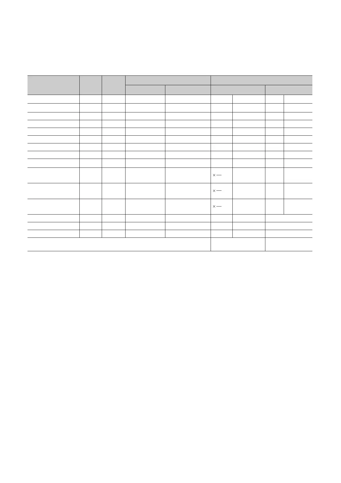
(2) Device point assignment example
The following table shows device point assignment examples based on the device point assignment sheet in
Appendix.6.
*1 The points are fixed for the system. (Cannot be changed) However, the points for the step relay (S) can be changed to 0.
*2 Up to 32K points can be set for each device (60K for the internal relay and link relay).
*3 Enter the values multiplied or divided by the number shown in the Size (words) column.
Device name Symbol
Numeric
notation
Number of device point
*2
Restriction check
Points Range
Size (words)
*3
Points (bits)
*2
Input relay
*1
X 16 8K (8192) X0000 to X1FFF /16 512 ×1 8192
Output relay
*1
Y 16 8K (8192) Y0000 to Y1FFF /16 512 ×1 8192
Internal relay M 10 16K (16384) M0 to M16383 /16 1024 ×1 16384
Latch relay L 10 4K (4096) L0 to L4095 /16 256 ×1 4096
Link relay B 16 4K (4096) B0000 to B0FFF /16 256 ×1 4096
Annunciator F 10 1K (1024) F0 to F1023 /16 64 ×1 1024
Link special relay SB 16 2K (2048) SB0000 to SB07FF /16 128 ×1 2048
Edge relay V 10 1K (1024) V0 to V1023 /16 64 ×1 1024
Step relay
*1
S 10 8K (8192) S0 to S8191 /16 512 ×1 8192
Timer T 10 2K (2048) T0 to T2047 2304 ×2 4096
Retentive timer ST 10 2K (2048) ST0 to ST2047 2304 ×2 4096
Counter C 10 1K (1024) C0 to C1023 1152 ×2 2048
Data register D 10 14K (14336) D0 to D14335 ×1 14336 ⎯
Link register W 16 4K (4096) W0000 to W4095 ×1 4096 ⎯
Link special register SW 16 2K (2048) SW0000 to SW07FF ×1 2048 ⎯
Total
29568
(29696 or less)
63488
18
16
18
16
18
16
 Loading...