EasyManua.ls Logo

Mitsubishi L02CPU User Manual

Mitsubishi L02CPU
340 pages
To Next Page IconTo Next Page
To Previous Page IconTo Previous Page
Page #260 background imageLoading...
Page #260 background image
258
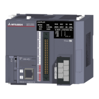
(b) When "High Speed Execution" is selected
*1 The Z0 value is changed to 3 in the interrupt program.
When writing data to the index register, use the ZPUSH or ZPOP instruction to save and restore the data. ( MELSEC-
Q/L Programming Manual (Common Instruction))
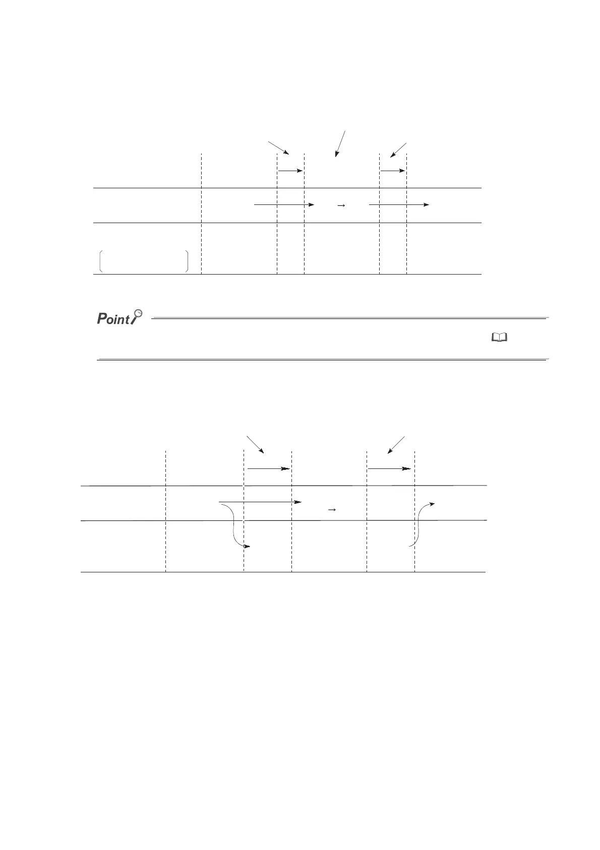
(3) Processing of file register block numbers
Execution program
Z0 = 1
Z0 = 0
Switching Restored
Passed Passed
Z0 = 0 Z0 = 0 Z0 = 0 Z0 = 0
Z0 = 3
Index register value
Save area of index register
for scan execution
type program
Scan execution
type program
Interrupt/fixed
scan execution
type program
Scan execution
type program
1) The CPU module does not save index register
values at program switching.
2) If data are written to the index register, the values of
the index register used in the scan execution type program
will be corrupted at program switching.
Z0 = 1 Z0 = 3
*
1
3) The index register
values are not saved.
[RSET K0]
Execution program
Save area
Switching
Restored
Block 1
Restored
Block 1Block 1Block 1 Block 1Block 0
Block 1
Passed
Saved
Block 1 0
Block No. of
file register
Scan execution
type program
Scan execution
type program
Interrupt/fixed
scan execution
type program
1) The CPU module saves the block numbers of
the file register and passes them at program
switching.
2) The CPU module restores the block
numbers of the file register saved at
program switching.

Table of Contents

Question and Answer IconNeed help?

Do you have a question about the Mitsubishi L02CPU and is the answer not in the manual?

Mitsubishi L02CPU Specifications

General IconGeneral
BrandMitsubishi
ModelL02CPU
CategoryController
LanguageEnglish

Summary

MITSUBISHI MELSEC-L CPU Module User's Manual

SAFETY PRECAUTIONS

Design Precautions

Essential safety guidelines for designing systems with the controller, covering circuits and operations.

Installation Precautions

Crucial steps for safely installing the programmable controller modules, including environment and interconnection.

Wiring Precautions

Important safety measures for correctly wiring the controller, covering grounding, terminals, and cable routing.

Startup and Maintenance Precautions

Precautions for safe startup, operation, and maintenance procedures, including handling batteries and static electricity.

PART 1 PROGRAMMING

CHAPTER 1 BASIC PROCEDURE FOR PROGRAMMING

Guides through the fundamental steps of PLC programming.

CHAPTER 1 BASIC PROCEDURE FOR PROGRAMMING

1.3 Creating a Program

Explains the fundamental steps and prerequisites for program creation.

1.5 Writing a Project to the CPU Module

Describes how to transfer the project, including memory formatting.

1.6 Checking an Operation of the CPU Module

Outlines procedures for verifying the CPU module's operation after programming.

CHAPTER 3 CPU MODULE FUNCTIONS

3.3 Watchdog Timer (WDT)

Details the watchdog timer for detecting hardware failures and program errors.

3.11 File Password 32

Explains how to protect files stored in the CPU module with passwords.

3.13 Remote Operation

Details methods for controlling CPU module operations remotely.

3.21 Writing Programs in RUN Status

Describes online program changes while the CPU module is running.

3.23 Self-Diagnostic Function

Covers the CPU module's self-diagnostic capabilities for error detection.

3.24 Error Clear

Explains how to clear detected continuation errors by type.

3.30 CPU Module Change Function with SD Memory Card

Explains data backup and restoration using an SD memory card for module replacement.

Appendix 1 Parameter Setting

Appendix 1.2 PLC Parameter

Details various PLC parameter settings including name, system, file, RAS, boot, and program.

Appendix 1.4 Remote Password setting

Provides screens and details for setting remote passwords for access control.

Appendix 1.2 PLC Parameter

2. PLC System Setting

Configures system-level parameters for CPU module operation.

4. PLC RAS Setting

Configures Reliability, Availability, and Serviceability (RAS) functions.

9. I/O Assignment Setting

Configures the connecting status and assignments of modules in the system.

Related product manuals