EasyManua.ls Logo

Mitsubishi L02CPU User Manual

Mitsubishi L02CPU
340 pages
To Next Page IconTo Next Page
To Previous Page IconTo Previous Page
Page #63 background imageLoading...
Page #63 background image
61
CHAPTER 2 APPLICATION OF PROGRAMMING
2
2.8 Executing Multiple Programs
2.8.1 Initial execution type program
(2) Initial scan time
Initial scan time is the execution time of initial execution type program. When multiple programs are executed, the
initial scan time will be the time required for completing all the initial execution type program execution.
Since the CPU module stores the initial scan time into the special register (SD522 and SD523), the initial scan
time can be checked by monitoring SD522 and SD523. (Accuracy: ±0.1ms)
If the stored values in SD522 and SD523 are 3 and 400 respectively, the initial scan time is 3.4ms
Even if the WDT instruction (instruction that resets the watchdog timer) is executed in the program, the
measurement of the initial scan time continues.
When an interrupt program or fixed scan execution type program is executed before completion of the initial execution type
program execution, the execution time of the executed program will be added to the initial scan time. When an interrupt
program of fixed scan execution type program is executed before completion of the initial execution type program execution,
the execution time of the executed program will be added to the initial scan time.
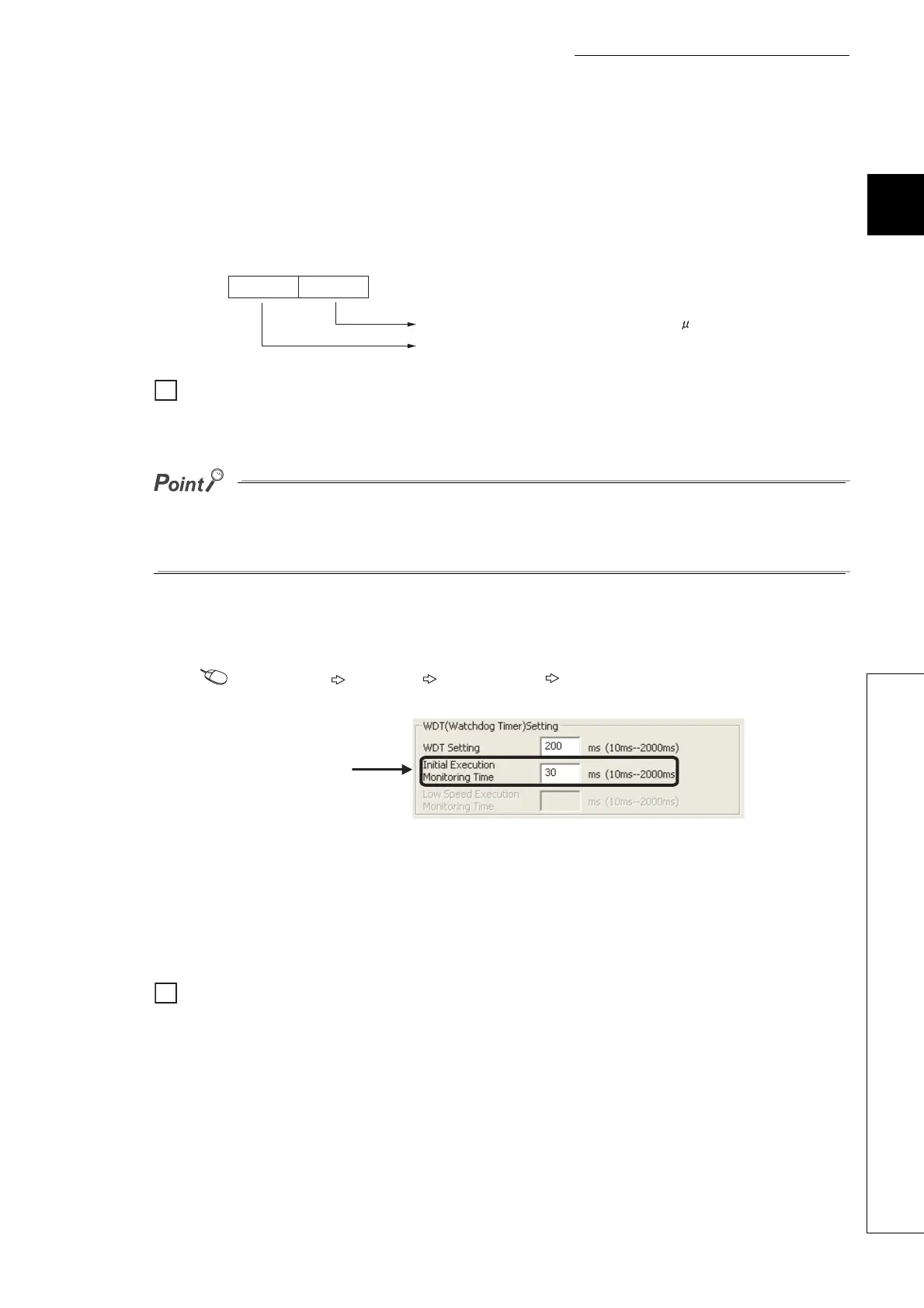
(3) Initial execution monitoring time
Initial execution monitoring time is a timer for monitoring initial scan time.
Project window [Parameter] [PLC Parameter] [PLC RAS]
The setting range is 10 to 2000ms (in increments of 10ms). No default value is set.
(4) Precautions on programming
Initial execution type programs do not support the instructions that require several scans (instructions with
completion device).
SEND, RECV and similar instructions
SD522 SD523
Stores the initial scan time of 1ms or less (unit: s)
Stores the initial scan time. (in increments of 1ms)
Ex.
Ex.
Set initial execution
monitoring time.
Ex.
Ex.

Table of Contents

Question and Answer IconNeed help?

Do you have a question about the Mitsubishi L02CPU and is the answer not in the manual?

Mitsubishi L02CPU Specifications

General IconGeneral
BrandMitsubishi
ModelL02CPU
CategoryController
LanguageEnglish

Summary

MITSUBISHI MELSEC-L CPU Module User's Manual

SAFETY PRECAUTIONS

Design Precautions

Essential safety guidelines for designing systems with the controller, covering circuits and operations.

Installation Precautions

Crucial steps for safely installing the programmable controller modules, including environment and interconnection.

Wiring Precautions

Important safety measures for correctly wiring the controller, covering grounding, terminals, and cable routing.

Startup and Maintenance Precautions

Precautions for safe startup, operation, and maintenance procedures, including handling batteries and static electricity.

PART 1 PROGRAMMING

CHAPTER 1 BASIC PROCEDURE FOR PROGRAMMING

Guides through the fundamental steps of PLC programming.

CHAPTER 1 BASIC PROCEDURE FOR PROGRAMMING

1.3 Creating a Program

Explains the fundamental steps and prerequisites for program creation.

1.5 Writing a Project to the CPU Module

Describes how to transfer the project, including memory formatting.

1.6 Checking an Operation of the CPU Module

Outlines procedures for verifying the CPU module's operation after programming.

CHAPTER 3 CPU MODULE FUNCTIONS

3.3 Watchdog Timer (WDT)

Details the watchdog timer for detecting hardware failures and program errors.

3.11 File Password 32

Explains how to protect files stored in the CPU module with passwords.

3.13 Remote Operation

Details methods for controlling CPU module operations remotely.

3.21 Writing Programs in RUN Status

Describes online program changes while the CPU module is running.

3.23 Self-Diagnostic Function

Covers the CPU module's self-diagnostic capabilities for error detection.

3.24 Error Clear

Explains how to clear detected continuation errors by type.

3.30 CPU Module Change Function with SD Memory Card

Explains data backup and restoration using an SD memory card for module replacement.

Appendix 1 Parameter Setting

Appendix 1.2 PLC Parameter

Details various PLC parameter settings including name, system, file, RAS, boot, and program.

Appendix 1.4 Remote Password setting

Provides screens and details for setting remote passwords for access control.

Appendix 1.2 PLC Parameter

2. PLC System Setting

Configures system-level parameters for CPU module operation.

4. PLC RAS Setting

Configures Reliability, Availability, and Serviceability (RAS) functions.

9. I/O Assignment Setting

Configures the connecting status and assignments of modules in the system.

Related product manuals