10/05 AWB8230-1541GB
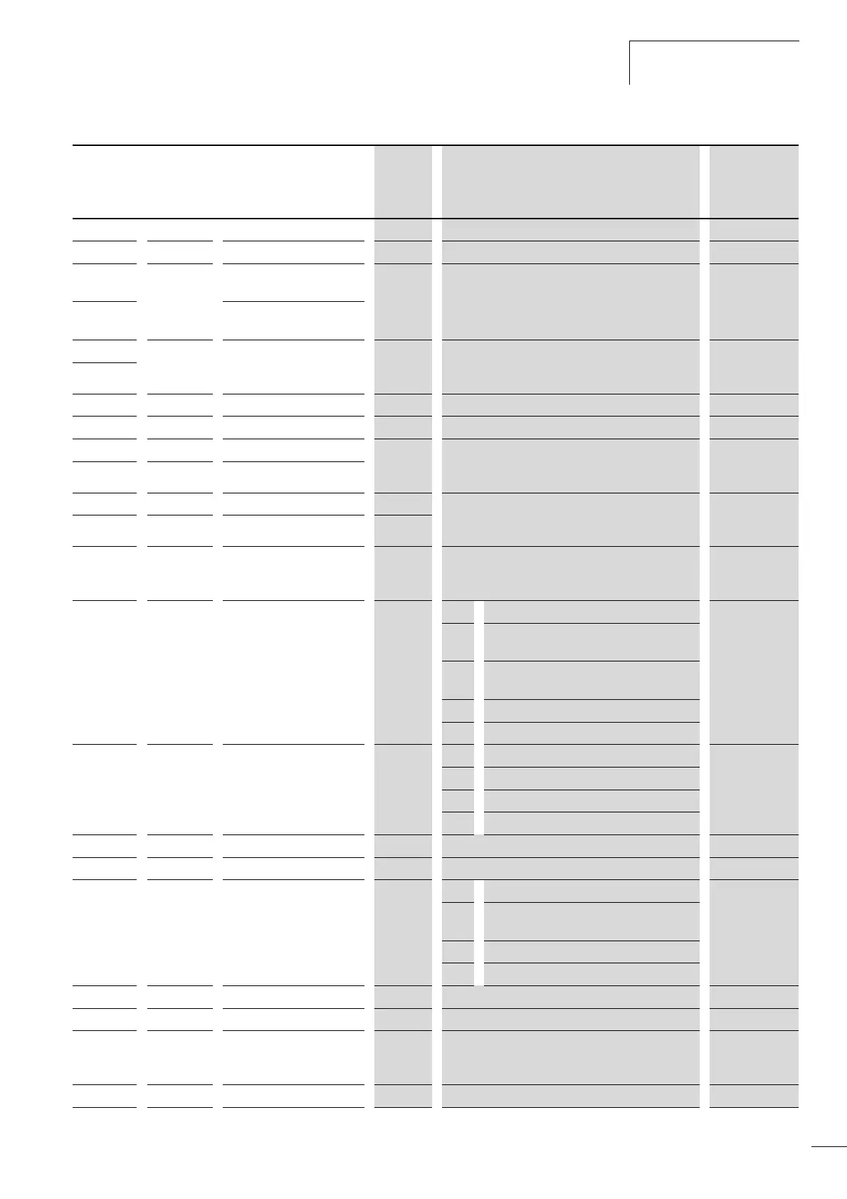
Holding register (word
variable)
165
100C d013 Indication – output voltage ro 0 – 600 V (1 V) 1 [%]
100D d014 Reserved ro – –
100E d016 Indication – operation time
counter (MSB)
ro 0 – 9999 (1 h)
10000 – 99990 (10 h)
100000 – 999000 (1000 h)
1 [h]
100F Indication – operation time
counter (LSB)
1010 d017 Indication – mains On time ro 0 – 9999 (1 h)
10000 – 99990 (10 h)
100000 – 999000 (1000 h)
1 [h]
1011
1012 – Reserved
rw – –
1013 – Reserved rw – –
1014 F002 Acceleration time 1 (MSB) rw 0.01 – 99.99 (0.01 s)
100.0 – 999.9 (0.1 s)
1000 – 3000 (1 s)
0.01 [s]
1015 F002 Acceleration time 1 (LSB)
1016 F003 Deceleration time 1 (MSB) rw 0.01 – 99.99 (0.01 s)
100.0 – 999.9 (0.1 s)
1000 – 3000 (1 s)
0.01 [s]
1017 F003 Deceleration time 1 (LSB) rw
1018 F004 Direction of rotation –
function of START key
(keypad)
rw 00: Clockwise rotating field ( FWD)
01: Anticlockwise rotating field (REV)
–
1019 A001 Reference value source
selection
rw 00: Potentiometer (keypad) –
01: Analog input: Control signal terminals O
and OI
02: Digital input (function PNU F001 or A020)
and keypad
03: Serial interface (Modbus)
10: Calculator (calculated value of CAL)
101A A002 Start signal source selection rw 01: Digital input (FWD/REV) –
02: START button (keypad)
03: Serial interface (Modbus)
04: Potentiometer (optional keypad DEX-KEY-6)
101B A003 Base frequency
rw 30 – 400 Hz, up to value of PNU A004 [Hz] 1 [Hz]
101C A004 End frequency (fmax) rw 30 – 400 Hz 1 [Hz]
101D A005 Analog input – selection
(AT)
rw 00: analog inputs O and/or OI –
01: analog inputs O and OI (digital input is
ignored)
02: Analog input O or potentiometer (keypad)
03: Analog input OI or potentiometer (keypad)
101E A006 Reserved rw – –
101F A011 Reserved rw – –
1020 A011 Analog input (O-L) –
frequency at minimum
reference value
rw 0 – 400 Hz 0.1 [Hz]
1021 A012 Reserved
rw – –
Holding
register
Function
code
Name
Access
rights
Value range Manipulated
variable
hex