SECTION 3: WIRING AND INSTALLATION T200 User's Manual
PAGE 3-67
3.14.7 T200-610 and T200-710 Motor Power Cable Shield Connection
The motor-power-cables shields should be clamped to a suitable Protective Earth bar made available where the cables
enter the user cabinet. The connection should be made 360degrees if possible around the cable shield, using P-Clips or
other means to ensure good high frequency contact with the Protective Earth
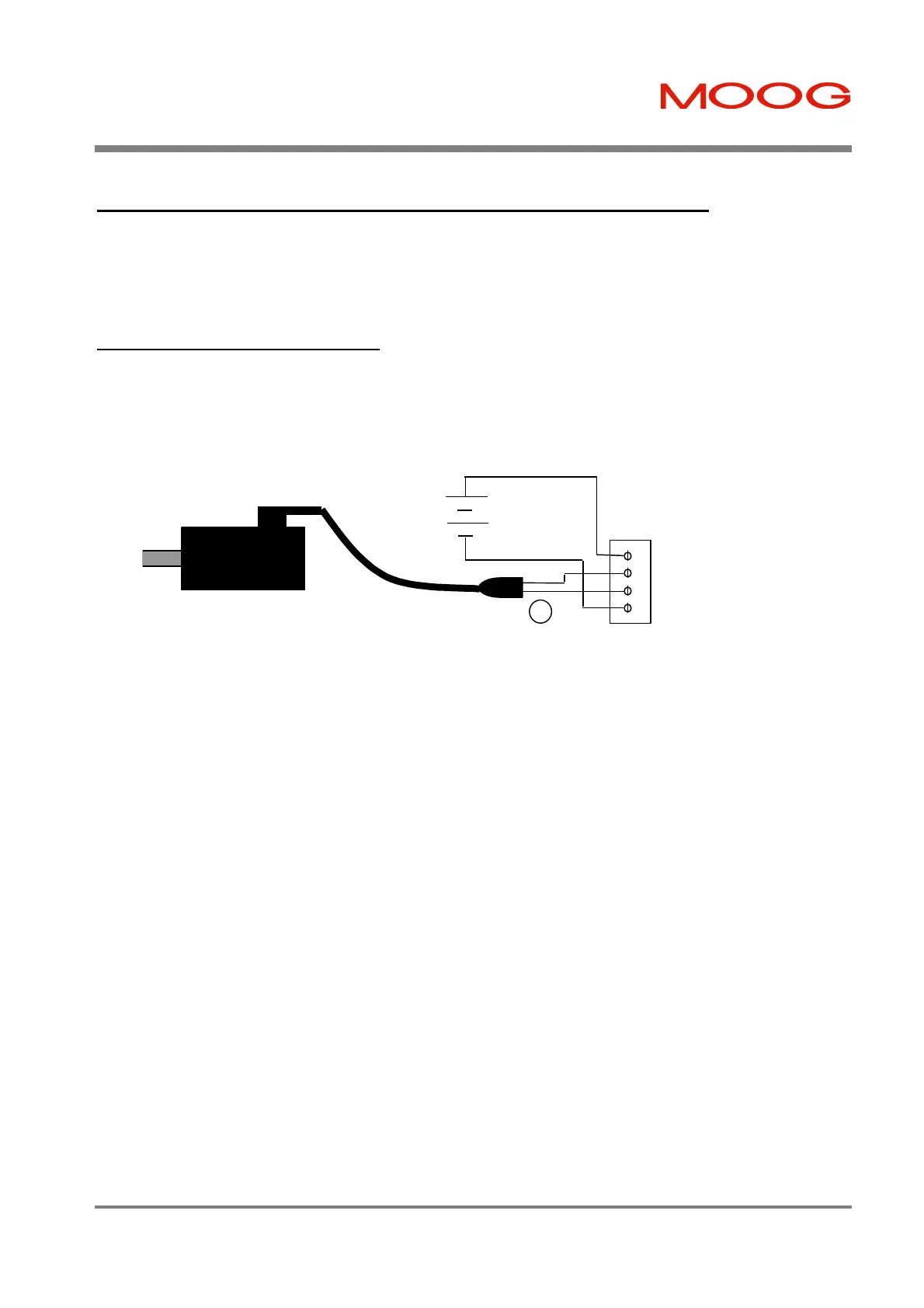
3.14.8 Motor Brake Connection
The T200 provides a motor break relay at connector TB7. The user supplies a 24Vd.c., Power Supply Unit for the brake
connections. Note that the current consumption of the different brake types is specified in Section 4.5.7.
Figure 3.38:- Motor Brake Cabling
* The pins of the brake terminals at the motor cable connector end depend upon the cable size. Refer to Figure 3.34 for
details.
TB7
1 24V+
2 Brake+
3 Brake-
4 24V_RET
User
Supplied
24V PSU
Motor
Power
Cable
Artisan Technology Group - Quality Instrumentation ... Guaranteed | (888) 88-SOURCE | www.artisantg.com