T200 User's Manual SECTION 3: WIRING AND INSTALLATION
PAGE 3-90
3.19 T200 User Visual Indications
The T200 product family provides the following diagnostic information to the user:-
• On T200-X10 models (with integral High Power PSU), three power monitoring LED's are provided for user
diagnostic purposes (BUS ACTIVE, MAINS APPLIED, REGEN ACTIVE in Figure 3.56).
• On T200-X00 models (without integral High Power PSU), one power monitoring LED is provided for user
diagnostic purposes (BUS ACTIVE in Figure 3.57).
• On all models a 7-segment display is provided to display user diagnostic information.
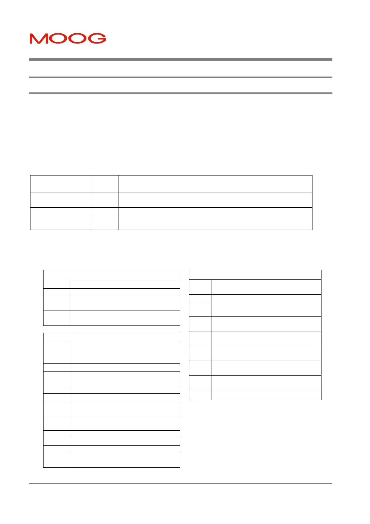
LED Name Color Description of Operation
BUS ACTIVE Green Illuminates when high voltage is present on the T200 DC Bus terminals
(on connector TB3)
MAINS APPLIED Amber Illuminates when A.C. Mains is applied (on connector TB2)
REGEN ACTIVE Amber Illuminates when motor kinetic energy regeneration is active (voltage
applied via connector TB1)
7-Segment Display User Indication Codes
The appropriate characters of the code will appear at about 0.5 second intervals. Fault conditions will be displayed as
the highest priority, followed by abnormal conditions (warnings) and then normal operation codes.
Normal Operation Display
U1 AC Mains high power is not applied
P T200 is self-parameterisating.
O Indicates that no faults are present and
the drive is powered correctly.
E High power is presently applied to the
motor phases (i.e T200 is enabled).
Abnormal Condition Display
[.] The period indicates that servo-drive
current levels have been limited due to
thermal self protection reasons.
E2/U2
Motor temperature has exceeded 130° C.
E3/U3 Bridge temperature has exceeded a
defined warning threshold.
E4/U4 Position Following Error occurring.
E5/U5 Velocity Following Error occurring.
E6/U6 The continuous rating of the external
regeneration resistor has been exceeded.
E7/U7 Servo-drive Controller Area Network
(CAN) communications error.
E8/U8 Limit switches have been activated.
U9 Internal software programming error.
Ua Quick-Stop function active.
Ub Incremental Encoder has been
disconnected.
Fault Condition Display
F1 Power Amplifier over-current fault has
occurred.
F2 DC-Bus voltage has exceeded 400V.
F3 Only for T200-X10 models, the internal
regeneration circuitry fuse has blown.
Only for T200-X10 models, the rectifier
heat-sink temperature is too high.
F5 The Temperature of the Power Amplifier
heat-sink is too high.
F6 The Temperature of the motor has
exceeded 155° C.
F7 Fatal programming error or critical
software error has occurred.
F8 Resolver position transducer error has
occurred.
F9
Internal ± 15V control voltage loss.
Artisan Technology Group - Quality Instrumentation ... Guaranteed | (888) 88-SOURCE | www.artisantg.com