SECTION 7: WINDRIVE T200 User's Manual
PAGE 7-37
d) Digital Speed Input Reference
Figure 7.38: Digital Speed Input Dialog Box
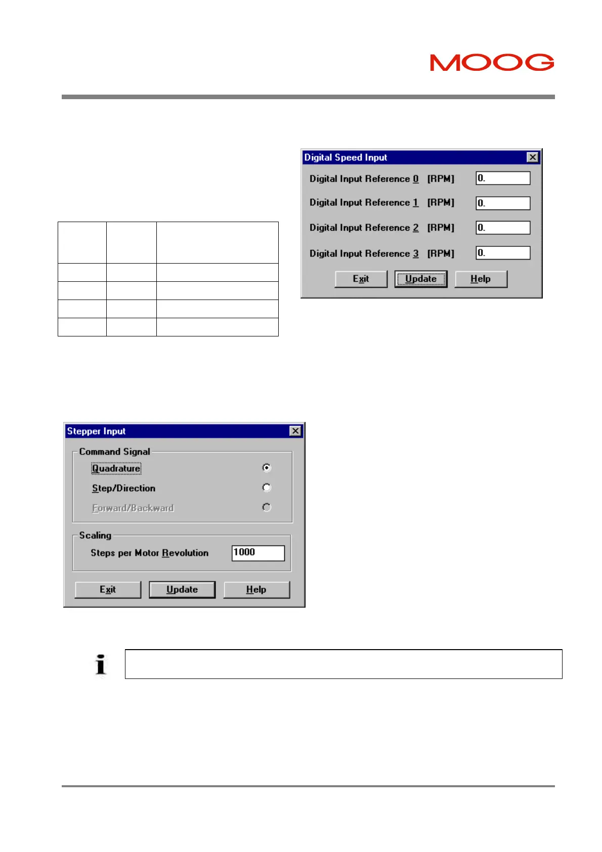
e) Stepper Input Reference
The Stepper Input Position Reference is set-up using the dialog shown below. It can be entered by clicking the Set-up
button in the Reference Source dialog.
Figure 7.39: Stepper Input Dialog Box
f) Custom POINT Reference
If integral motion control is used as a command source, the Custom POINT option is selected. This option is only
available if the T200 embedded software version is 'Pn', where n is the software revision. Use of this software is covered
in the 'T200-POINT User's Manual' MOOG Part Number C09661-001.
The Digital Speed Input functionality is described in
Section 6. The reference speeds corresponding to the
state of the 2 digital inputs are specified in units of
RPM. Enter this dialog via Set-up from the Reference
Source dialog.
PROG_
SPRD_1
Status
PROG_
SPRD_0
Status
Speed Reference Used
0 0 Digital Input Reference 0
0 1 Digital Input Reference 1
1 0 Digital Input Reference 2
1 1 Digital Input Reference 3
Table 7.3: Digital Input Speed Programming
Two formats for the protocol are detailed in
Section 6. One of the two can be selected by
choosing one of the Quadrature or Step/Direction
radio buttons in the Command-Signal field.
Scaling is set by the number of stepper pulses per
revolution. Note that in Quadrature mode, there is
an effective resolution increase by a factor of 4
over other modes because each pulse edge can be
used as a position increment. For example if the
Steps per Motor Revolution field is set at 10, the
number of discrete position steps per revolution
will correspond to 40 if a Quadrature type
Command Signal was selected. However only 10
such steps will exist if the Step/Direction mode is
chosen.
NOTE - The operation of the stepper interface is specified in detail in Section 6.11.
Artisan Technology Group - Quality Instrumentation ... Guaranteed | (888) 88-SOURCE | www.artisantg.com