T200 User's Manual SECTION 9: CAN INSTALLATION
PAGE 9-4
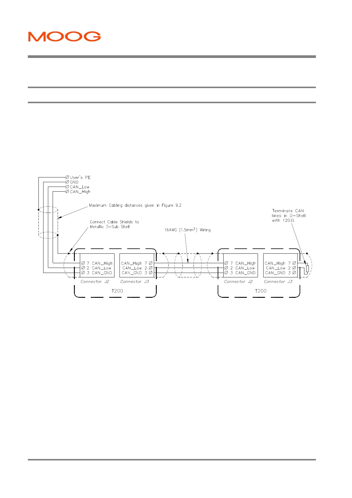
9.2 CAN Cable Wiring
The CAN-In and CAN-Out ports at J2 and J3 of the T200 provide the means to daisy-chain the CAN cabling between
T200 units. Note:-
1. CAN lines must be terminated in a 120Ohm resistance, between the positive and negative terminals (CAN-High and
CAN-Low).
2. The CAN circuitry is isolated from the T200 logic power. An internal DC/DC – converter generates the supply
voltage for the isolated CAN interface.
Figure 9.1:- CAN Wiring and Termination
Artisan Technology Group - Quality Instrumentation ... Guaranteed | (888) 88-SOURCE | www.artisantg.com