TROUBLE DIAGNOSIS
MTC-71
C
D
E
F
G
H
I
K
L
M
A
B
MTC
Revision: January 2005 2004 Quest
SYSTEM DESCRIPTION
Component Parts
Defroster door control system components are:
● Front air control
● Defroster door motor
System Operation
The front air control determines defroster door position based on the position of the mode switch. When the
mode switch is in the defroster position, the defroster door motor rotates directing air to the defroster ducts.
When any mode other than defroster is selected, the defroster motor rotates in the opposite direction closing
off air flow to the defroster ducts.
COMPONENT DESCRIPTION
Defroster door motor
The defroster door motor is attached to the front heater & cooling
unit. The front air control sends a voltage to rotate to the defroster
door directing the air flow either to the defroster ducts, or to the floor
ducts, depending on which way the voltage and ground are applied
to the motor leads. Motor rotation is conveyed to a lever which acti-
vates the defroster door.
DIAGNOSTIC PROCEDURE FOR DEFROSTER DOOR MOTOR
1. CHECK RESULT FROM FRONT AIR CONTROL SELF-DIAGNOSIS
Self-diagnosis code 62 is present.
OK or NG
OK >> GO TO 2.
NG >> Replace front air control. Refer to MTC-116, "
FRONT AIR CONTROL" .
2. CHECK POWER SUPPLY CIRCUITS FOR DEFROSTER DOOR MOTOR
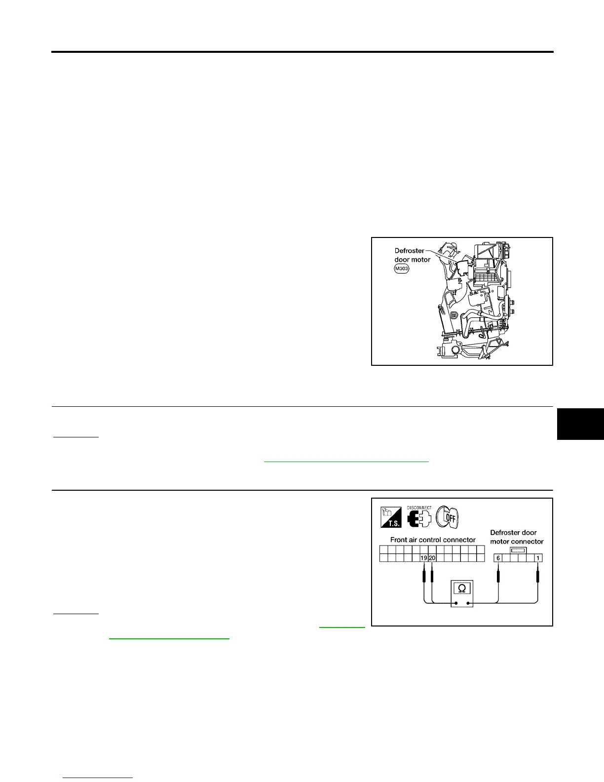
1. Disconnect front air control connector and defroster door motor
connector.
2. Check continuity between front air control harness connector
M49 terminal 19 (W/B) and defroster door motor connector
M303 terminal 1 (W/B) and between front air control harness
connector M49 terminal 20 (W) and defroster door motor con-
nector M303 terminal 6 (W).
OK or NG
OK >> Replace defroster door motor. Refer to MTC-129,
"Removal and Installation" .
NG >> Repair or replace harness as necessary.
LJIA0063E
Continuity should exist.
LJIA0064E