MTC-58
TROUBLE DIAGNOSIS
Revision: January 2005 2004 Quest
SYSTEM DESCRIPTION
Component Parts
Mode door control system components are:
● Front air control
● Mode door motor
● PBR (built into mode door motor)
System Operation
The mode door position (vent, B/L, foot, and defrost) is set by the front air control by means of the mode door
motor. When a mode door position is selected on the front air control, voltage is applied to one circuit of the
mode door motor while ground is applied to the other circuit, causing the mode door motor to rotate. The direc-
tion of rotation is determined by which circuit has voltage applied to it, and which one has ground applied to it.
The front air control monitors the mode door position by measuring the voltage signal on the PBR circuit.
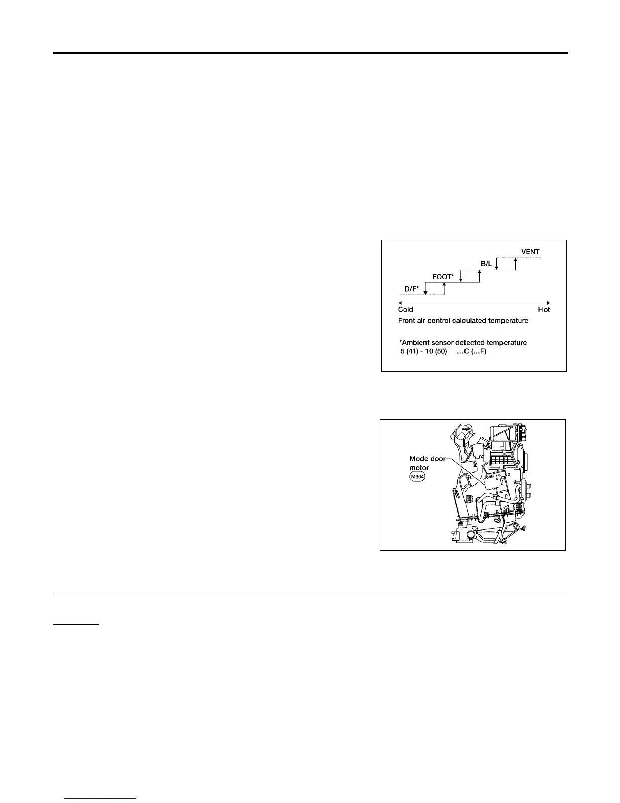
Mode Door Control Specification
COMPONENT DESCRIPTION
Mode Door Motor
The mode door motor is attached to the heater & cooling unit. It
rotates so that air is discharged from the outlet set by the front air
control Motor rotation is conveyed to a link which activates the mode
door.
DIAGNOSTIC PROCEDURE FOR MODE DOOR MOTOR
1. CHECK RESULT FROM FRONT AIR CONTROL SELF-DIAGNOSIS
Self-diagnosis code 92 is present.
Yes or No
Yes >> GO TO 2.
No >> GO TO 3.
WJIA0434E
WJIA0424E