TROUBLE DIAGNOSIS
MTC-113
C
D
E
F
G
H
I
K
L
M
A
B
MTC
Revision: January 2005 2004 Quest
COMPONENT INSPECTION
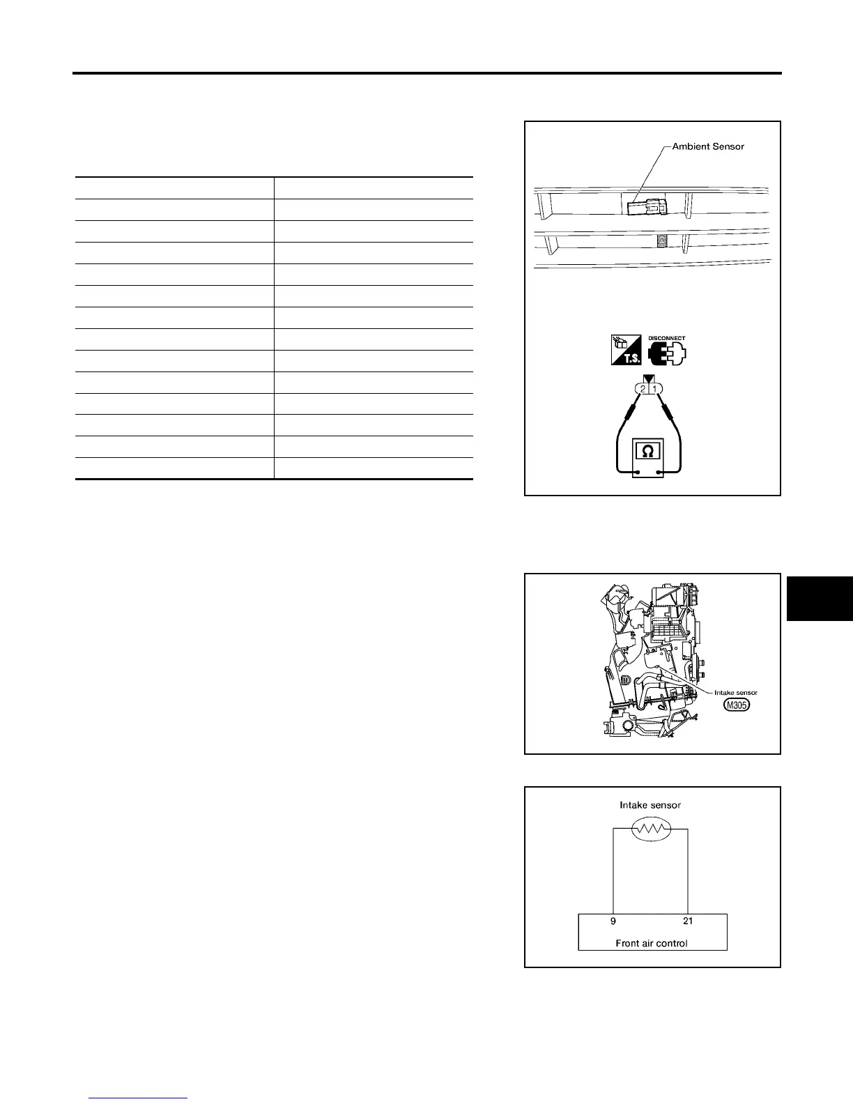
Ambient Sensor
After disconnecting ambient sensor connector, measure resistance
between terminals 2 and 1 at sensor component side, using the table
below.
If NG, replace ambient sensor.
Intake Sensor Circuit EJS001SY
COMPONENT DESCRIPTION
Intake Sensor
The intake sensor is located on the heater & cooling unit. It converts
temperature of air after it passes through the evaporator into a resis-
tance value which is then input to the front air control
DIAGNOSTIC PROCEDURE FOR INTAKE SENSOR
SYMPTOM: Intake sensor circuit is open or shorted. (56 or 57 is indi-
cated on front air control as a result of conducting Self-diagnosis).
Temperature °C (°F) Resistance kΩ
−15 (5) 12.73
−10 (14) 9.92
−5 (23) 7.80
0 (32) 6.19
5 (41) 4.95
10 (50) 3.99
15 (59) 3.24
20 (68) 2.65
25 (77) 2.19
30 (86) 1.81
35 (95) 1.51
40 (104) 1.27
45 (113) 1.07
WJIA0339E
WJIA0482E
WJIA0464E