TROUBLE DIAGNOSIS
MTC-111
C
D
E
F
G
H
I
K
L
M
A
B
MTC
Revision: January 2005 2004 Quest
Ambient Sensor Circuit EJS001SV
COMPONENT DESCRIPTION
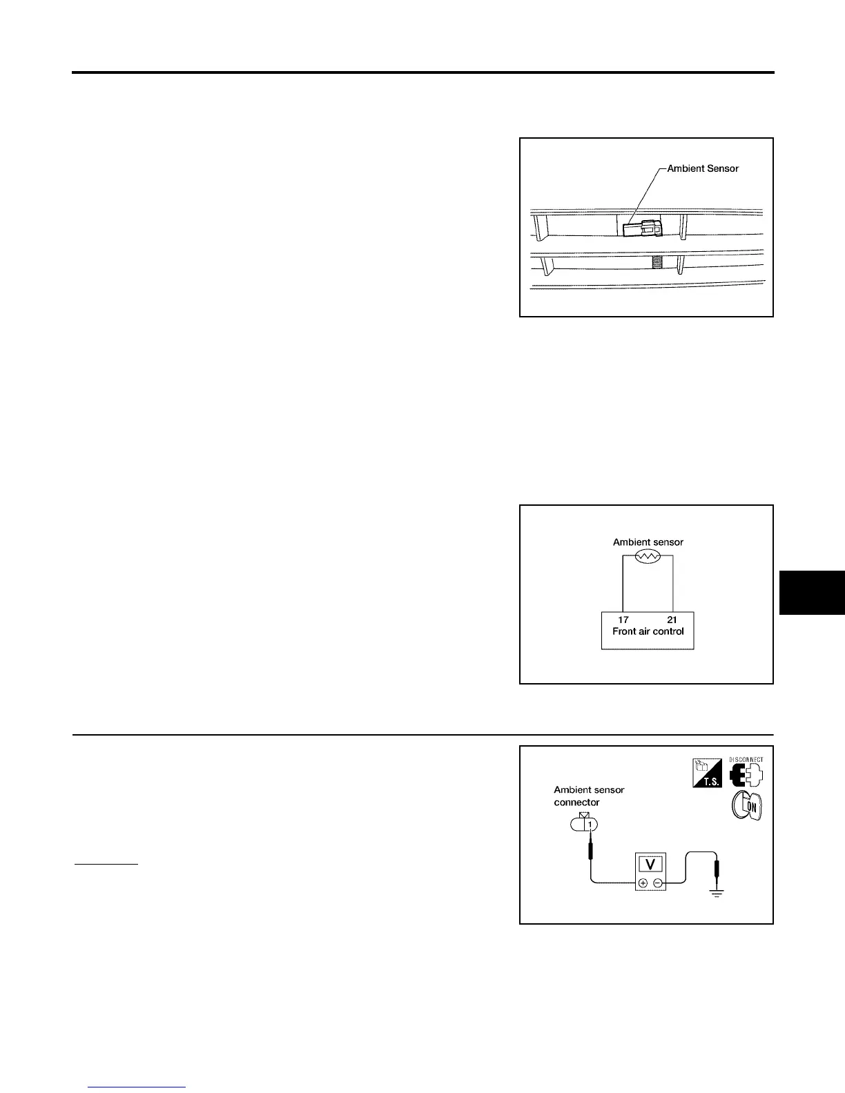
Ambient Sensor
The ambient sensor is attached on the radiator core support (left
side). It detects ambient temperature and converts it into a resis-
tance value which is then input into the front air control.
AMBIENT TEMPERATURE INPUT PROCESS
The front air control includes a processing circuit for the ambient sensor input. However, when the tempera-
ture detected by the ambient sensor increases quickly, the processing circuit retards the front air control func-
tion. It only allows the front air control to recognize an ambient temperature increase of 0.33°C (0.6°F) per 100
seconds.
This prevents constant adjustments due to momentary conditions, such as stopping after high speed driving.
Although the actual ambient temperature has not changed, the temperature detected by the ambient sensor
will increase. This is because the heat from the engine compartment can radiate to the front grille area, loca-
tion of the ambient sensor.
DIAGNOSTIC PROCEDURE FOR AMBIENT SENSOR
SYMPTOM: Ambient sensor circuit is open or shorted. (40 or 41 is
indicated on front air control As a result of conducting the front air
control self-diagnosis)
1. CHECK VOLTAGE BETWEEN AMBIENT SENSOR AND GROUND
1. Disconnect ambient sensor connector.
2. Turn ignition switch ON.
3. Check voltage between ambient sensor harness connector E1
terminal 1 (O/B) and ground.
OK or NG
OK >> GO TO 2.
NG >> GO TO 4.
WJIA0338E
WJIA0456E
Approx. 5V
WJIA0977E