Machine Systems MY500 JetPrinter MYDATA
3 - 20 Rev. 0003 2008-06 P-030-0014-EN – Service Manual
Machine Electronics
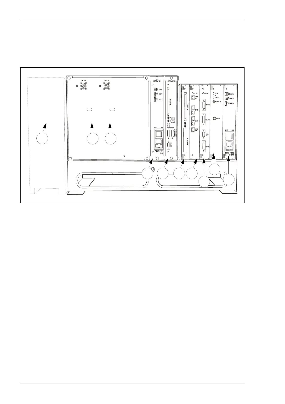
The following amplifier and control units are found in the machine behind the
front hood. Block diagrams describing these units are found in the next
section.
Units:
1. PC
Runs the JPSys machine software. The PC has a motion controller board,
a CAN interface board and a video frame grabber board.
The Amplifier box with a passive backplane, MOT–PBP, which connects the
following boards:
2. X–AMP
Servo amplifier for the X – motor drive.
3. Y–AMP
Servo amplifier for the Y – motor drive.
4. MOT–PIM
Power input module. Converts AC power to 24 VDC, which is supplied
to the boards in the amplifier box through the MOT–PBP. Power is also
supplied to SAF–CAN boards in the safety loop including light tower
and air control electronics.
Figure 3-22. Machine electronic units.
1
3
2
4
5
6
7
8
9
1
0