DS1000/2000 Correspondence Course
DS2000 System Installation
96 ◆ DS1000/2000 Workbook NEC America
❏
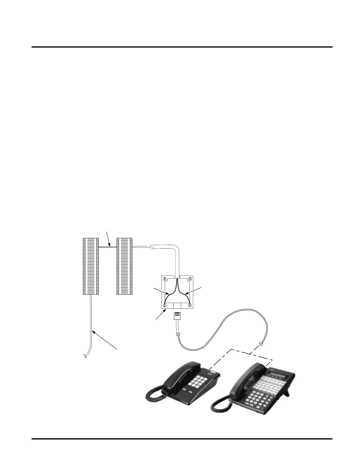
Run cabling for each extension, install mod jacks, and connect
the telephones.
Each 16DSTU PCB connects 16 digital extensions. Each 8ASTU PCB con-
nects 8 analog extensions. Each 4ASTU PCB connects 4 analog extensions.
1. Insert the mod jacks into the appropriate connector on the PCB.
Use the illustration in “Punch down the extension cables” (page
32) as a guide.
2. Install a modular jack for each extension within 6 feet of the telephone’s
location.
3. For each extension, run one-pair 24 AWG station cable from the cross-
connect block to the modular jack.
4. Terminate the station cable WHT/BLU - BLU/WHT leads to the RED
and GRN lugs in the modular jack.
5. Back at the main equipment location, run one pair of cross-connect wire
between the pins on the B block and cross-connect block to complete the
connection.
6. Install bridging clips as required.
You can also connect analog extensions to 2-OPX modules on the
DS2000 system. See Installing the 2-OPX Module on the DS2000
System on page 112.
625
Modular
Jack
25-Pair
Installation Cable
(P/N 80892)
BLK
YEL
RED
GRN
BLU-WHT
WHT-BLU
Cross
Connect
Block
One-Pair
Cross Connect
Station
Block
80000 - 36A

 Loading...