– 372 – NWA-008853-001 Rev.3.0
97ch4001.fm
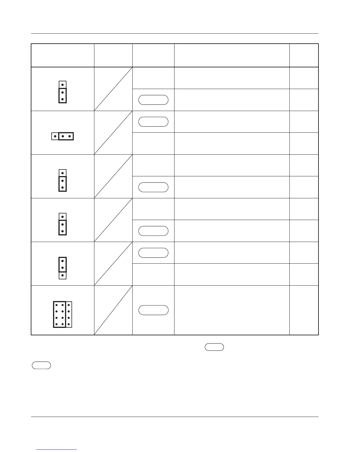
The figure in the SWITCH NAME column and the position of in the SETTING POSITION col-
umn indicate the standard setting of the switch. When the switch is not set as shown by the figure and
, the setting of the switch varies with the system concerned.
NOTE 1: Set the groove on the switch to the desired position.
Continued on next page
JPR0 (Jumper pin)
UP
Neutral grounding on the receiving line
is provided.
Neutral grounding on the receiving line
is not provided.
JPR1 (Jumper pin)
Line impedance: 100 Ω
LEFT Line impedance: 110 Ω
JPS (Jumper pin)
UP
Neutral grounding on the transmitting
line is provided.
Neutral grounding on the transmitting
line is not provided.
MAS (Jumper pin)
UP Clock Source
Clock Receiver
AISS (Jumper pin)
AIS signal is sent out when make-busy
or power on.
DOWN
AIS signal is not sent out when make-
busy or power on.
JP1 (Jumper pin)
Always set to LEFT
SWITCH NAME
SWITCH
NUMBER
SETTING
POSITION
FUNCTION CHECK
DOWN
RIGHT
DOWN
DOWN
UP
LEFT
PN-24CCTA (CCT)