– 386 – NWA-008853-001 Rev.3.0
97ch4001.fm
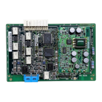
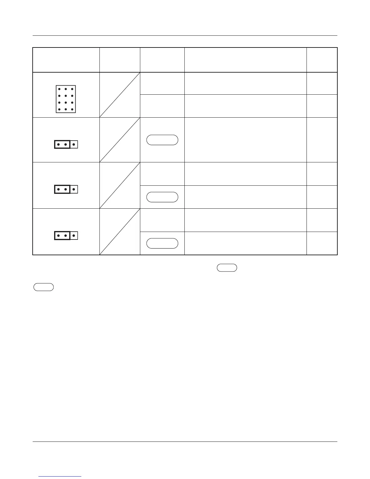
The figure in the SWITCH NAME column and the position of in the SETTING POSITION col-
umn indicate the standard setting of the switch. When the switch is not set as shown by the figure and
, the setting of the switch varies with the system concerned.
NOTE 1: Set the groove on the switch to the desired position.
NOTE 2: When the power is on, flip the MB switch to ON (UP position) before plugging/unplugging the
circuit card.
SWITCH NAME
SWITCH
NUMBER
SETTING
POSITION
FUNCTION CHECK
JP3 (Jumper pin)
RIGHT
Balanced transmission (For twisted-pair
cable) (for T1/E1)
LEFT
Unbalanced transmission (For coaxial
cable) (for E1)
JPRI (Jumper pin)
Not used
JPR (Jumper pin)
RIGHT
Neutral grounding on the receiving line
is provided
Neutral grounding on the receiving line
is not provided
JPT (Jumper pin)
RIGHT
Neutral grounding on the transmitting
line is provided
Neutral grounding on the transmitting
line is not provided
LEFT
LEFT
LEFT
JULY/01/2006
PN-DTA (CCT)