– 399 – NWA-008853-001 Rev.3.0
97ch4001.fm
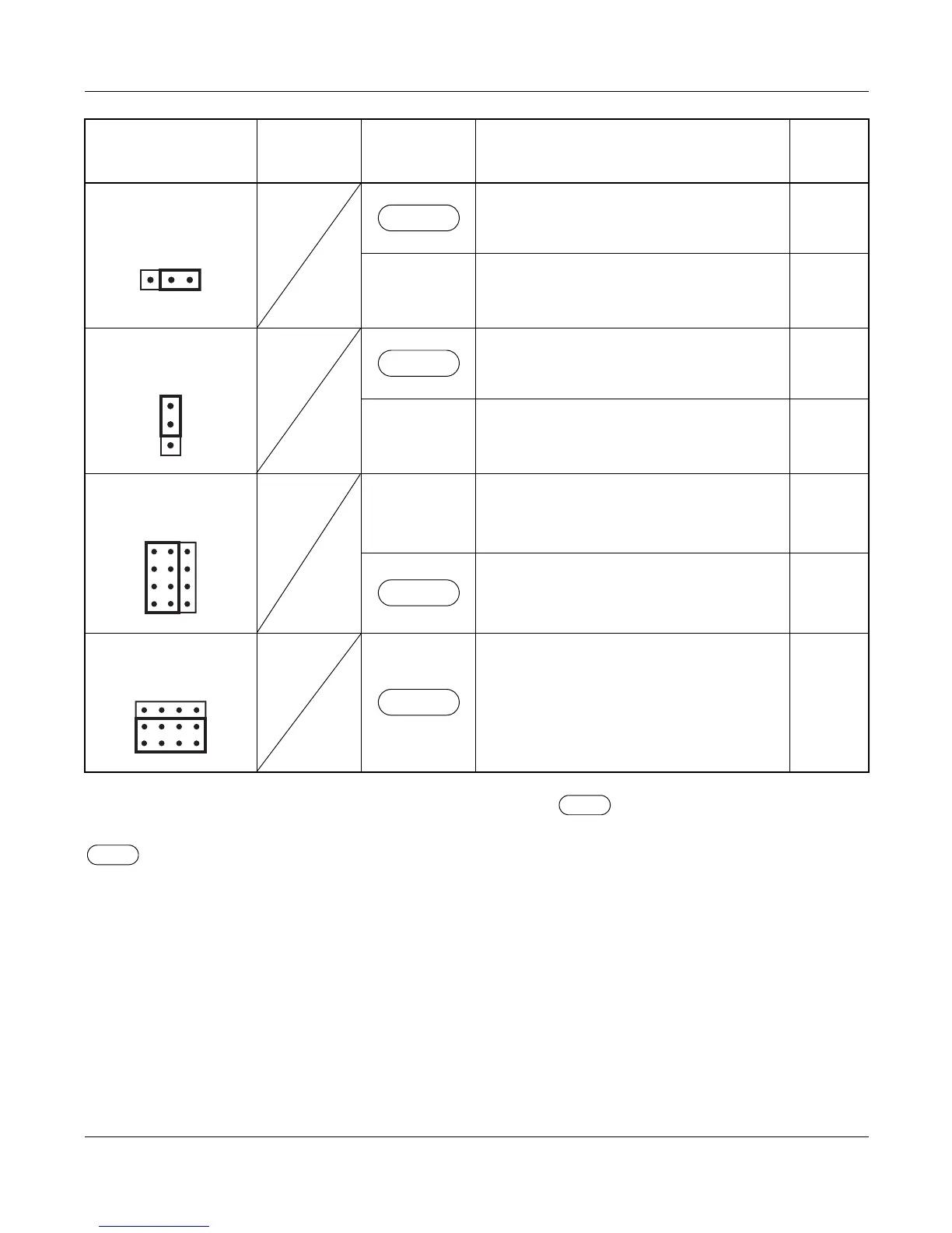
The figure in the SWITCH NAME column and the position of in the SETTING POSITION col-
umn indicate the standard setting of the switch. When the switch is not set as shown by the figure and
, the setting of the switch varies with the system concerned.
NOTE 1: Set the groove on the switch to the desired position.
NOTE 2: When the power is on, flip the MB switch to ON (UP position) before plugging/unplugging the
circuit card.
Continued on next page
JPS
(Jumper pin)
Balanced transmission
(For twisted-pair cable)
LEFT
TA is grounded on the transmission line
(For coaxial cable)
JPR
(Jumper pin)
Balanced transmission
(For twisted-pair cable)
DOWN
RA is grounded on the transmission line
(For coaxial cable)
JP
(Jumper pin)
RIGHT
Line impedance: 75 Ω
(For coaxial cable)
Line impedance: 120 Ω
(For twisted-pair cable)
JP1
(Jumper pin)
Always set to DOWN
SWITCH
NAME
SWITCH
NUMBER
SETTING
POSITION
FUNCTION CHECK
RIGHT
UP
LEFT
DOWN
PN-30DTC-C (DTI)
 Loading...


