3.3 Input and output terminals
FRA5087
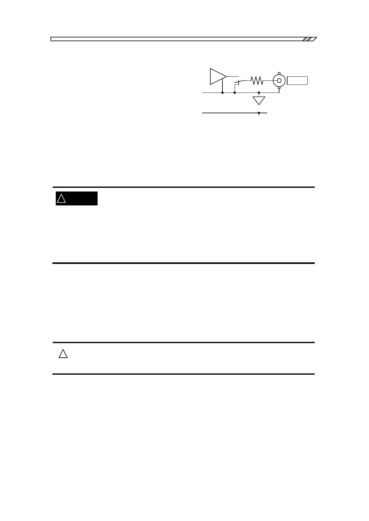
Oscillator output terminals (OSC)
The oscillator output terminal is electrically
insulated from both the cabinet and the analyzer
input terminals. The minimum allowable
breakdown voltage between the oscillator and
either the cabinet or the analyzer input terminals is
250 Vrms (measurement category I), when the accompanying insulated coaxial cable is used.
Restriction of 30 Vrms applies when a cable other than the accompanying cable is used. Note that
accidents due to electric shocks could occur, if the voltages exceeding the minimum breakdown
voltage are applied between the above mentioned insulated parts, leading to dielectric breakdown.
Refer to “3.4 Insulation breakdown voltages of input and output voltages” by all
means, when you make a measurement where high voltages are applied between any two of the
cabinets, CH1, CH2 and the oscillator.
Do NOT connect to any measurement target that exceeds 250 Vrms of
measurement Category I.
Doing so may result in insulation breakdown, imposing electrical shock.
You could be suffered from electric shocks when you measure high voltage
circuit signals. Use accessory coaxial cables of the insulation type by all
means, so that you cannot directly touch metallic portions of the BNC
connectors at the analyzer input terminals.
The output impedance is always 50 whether or not the output is “on”.
The maximum allowable output voltage is 10 V (for no load condition) for AC+DC, and the
maximum allowable output current is 100 mA.
The load resistance to be connected at the maximum output shall be no less than 50 .
The maximum output voltage to be set is 10 V (peak value) for AC+DC when a 50 load is
connected, where 5 V is applied for the 50 load.
Set the output voltage with a condition of no load connected.
The internal circuit will be damaged if you apply external signal voltages to the
output terminal. Never apply signal voltages to the output terminal.
[Notes]
A signal transmitted on a 50 series coaxial cable (e.g., RG-58A/u, 3D-2V, etc.) gets
approximately 5 ns per meter of time delay. This can be converted to the phase of 1.8 deg. per
meter for 1 MHz.
A 50 series coaxial cable has approximately 100 pF per meter of electrostatic capacitance.
If a signal is driven with a signal source resistance of 50 , the signal will be affected so that it
changes about -0.0043 dB in amplitude and -1.8 deg. in phase at 1 MHz.
Pay attention to the cleanliness of the contact of the connector. Dirt/stains at the connector
contact can cause approximately 0.03 dB of measurement errors depending upon measurement
conditions.