4.1 Burst oscillation
WF1946B 4-11
(3) Set STOP-LEVEL
① Use the
and
keys to produce the following display (STOP-LEVEL flashes).
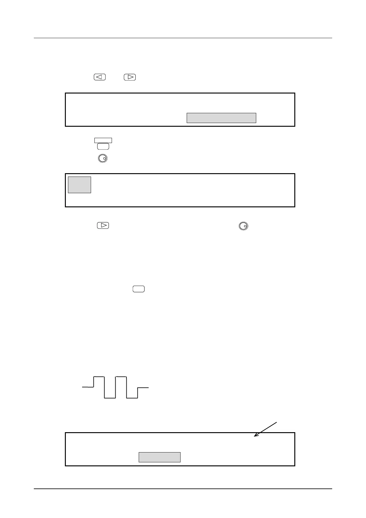
OFF
GATE:TYPE SOURCE STOP-LEVEL
② Press the
ENTER
key.
Turn the
MODIFY
dial to produce the following display (ON flashes).
ON 0.00 %
GATE:TYPE SOURCE STOP-LEVEL
③ Press the
key, then set the stop level with the keypad or
MODIFY
dial.
In this example, the setting is 0 %.
The stop level is the percentage with respect to the maximum positive (+100 %) and negative (-100 %)
amplitude.
④ After setting, press the
EXIT
key to release the setting mode.
The above selects sets burst oscillation (type: gate). Oscillation occurs when a high level signal is
applied to the TRIG/SWEEP IN connector. If the connection is open, oscillation continues due to
internal pullup.
Other settings:
• At the above settings, when the waveform is squarewave, a three squarewave is obtained such as
shown in the following figure.
• Internal gate source : A 50 % duty gate signal is generated at the following period for
oscillation start/stop. The gate rate is common for CH1 and CH2.
INT
H-ON
1.000ms
GATE:TYPE SOURCE STOP-LEVEL
(When stop level is off, the oscillation stops at
either high or low level.)