51
4 CONTROL Interface
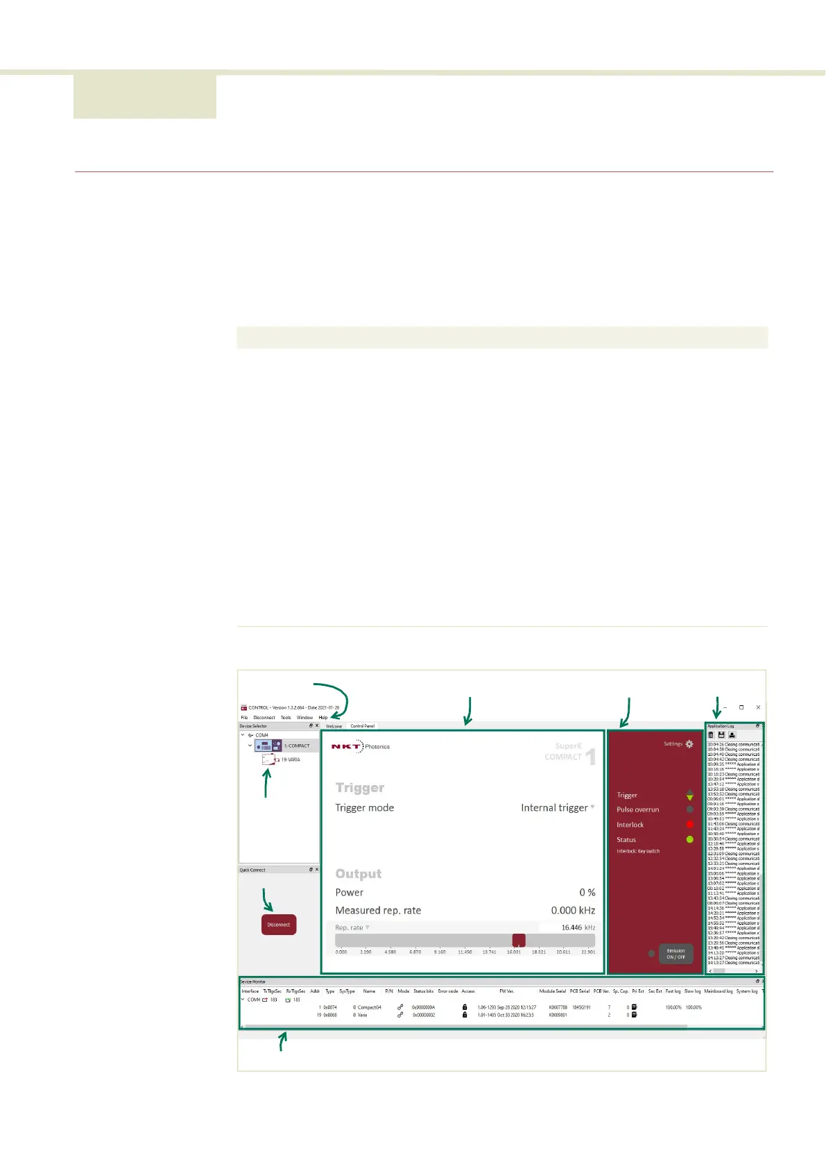
CONTROL overview
The CONTROL user interface includes multiple panels and a selection of menu
drop down items in the upper left corner. Using the Window drop down menu,
you can add or remove displayed panels. The panels can also be dragged within
the main window or into separate windows. Figure 23 shows CONTROL’s main
panels and menu; their functions are described in the table below.
Figure 23 CONTROL panel navigation
Panel Function See
Device
Selector
Selectable list of connected devices (lasers and
accessories) .
Connecting the laser to a
CONTROL PC on page 45
.
Quick Connect Provides a button when clicked, scans all
available PC ports for connected NKTP products.
Connecting to the laser on
page 53
Status Panel This panel displays the selected device status,
emission control and a CONTROL settings menu.
Status panel on page 54
Menu Items Five drop down menus with multiple functions.
CONTROL menu on page 58
Control Panel Includes adjustable settings for the laser and
accessories selected. Controls for repetition rate,
trigger voltage, and pulse burst count are
available.
Trigger mode on page 62
Application
Log
This panel displays a debugging log that can be
saved to a file.
Application log panel on
page 68
Device Monitor To also help debugging issues, this panel
displays multiple port and device module
parameters.
Device monitor on page 68
Menu Items
Control Panel
Status Panel
Application Log
Device Monitor
Quick
Connect
Device
Selector
List