Trigger input ports
82
Trigger input ports
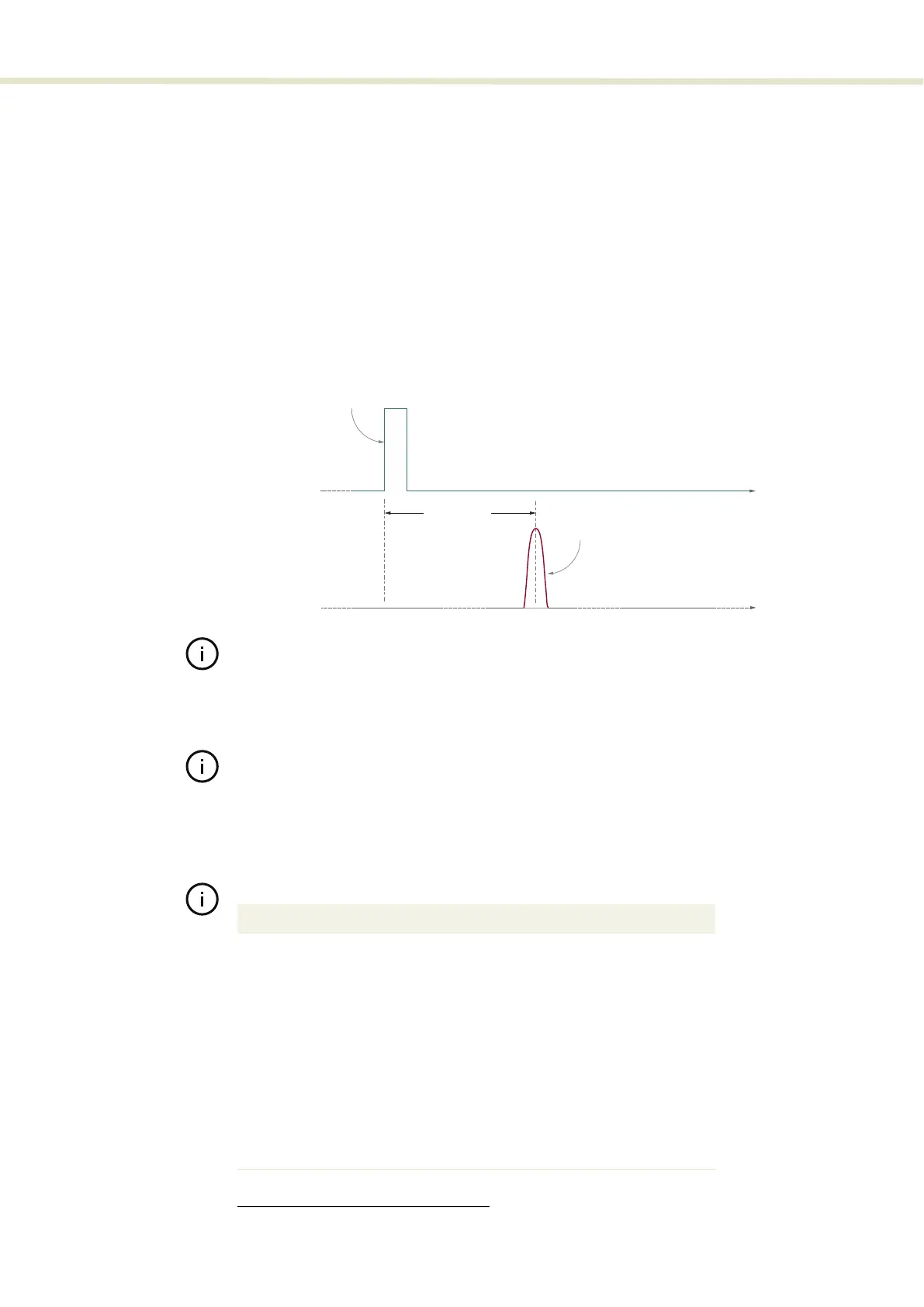
Coax trigger input This BNC port is considered a logic input. Figure 53 shows that when a signal
voltage connected to the port reaches the set trigger level, a pulse or burst is
emitted a short time after. The trigger timing advance and jitter specifications are
also shown in the figure. The trigger level is the voltage level at which, the laser
is triggered to emit a pulse or pulse burst. The voltage level is adjustable using
either the front panel controls (“Coax trig level” on page 41) or NKT Photonics
CONTROL management software (“Trigger level” on page 67). To reduce noise
sensitivity, the port has a hysteresis of approximately 1%.
Figure 53 Optical output delay and jitter vs. the COAX trig input port
Note: The pulse-to-pulse timing jitter, is in general a function of repetition rate, in-
creasing as the rate increases. For applications requiring minimal jitter, it is recom-
mended to lower the laser’s repetition rate to below 5 kHz and possibly as low as
1 to 2 kHz.
Note: When triggering the output pulse using either “Burst mode” or “Gated trig-
ger” mode, a lowered repetition rate can also help avoid a pulse overrun warning
situation. A pulse overrun
1
warning indicates that the laser could not output an op-
tical pulse before receiving the next trigger pulse, effectively reducing the number
of output pulses expected.
Table 10 Coax trigger input specifications
time
COAX trig input
Optical ouput
Trigger onset
Optical pulse
30-40 μs ±1 μs
1. See Status LEDs on page 30
Parameter Value
Nominal impedance
50 Ω
Peak voltage
minimum −7 V to maximum 7 V
Maximum power
0.8 W or 29 dBm RMS
Minimum pulse width
200 ns
Trigger level adjustable range
minimum 0 V to maximum 4 V
Hysteresis
~ 1%
Connector type
BNC
Maximum trigger frequency
200 kHz