27
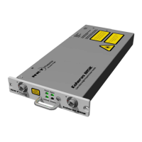
Rear panel interfaces
Enter button
When pressed this button either enters a selected menu sub-level or confirms a
setting or function within the menu system.
Selection dial The dial is used with the display and return button to configure, operate and view
the laser status.
ON/OFF switch Turns power ON or OFF.
Key switch Key access control of laser emission, when set to OFF, emission is not permitted.
The switch also resets the interlock alarm when cycled from ON to OFF and back
ON, see “Connecting the safety interlock” on page 75.
Note: Remove and secure the key to help prevent unauthorized access.
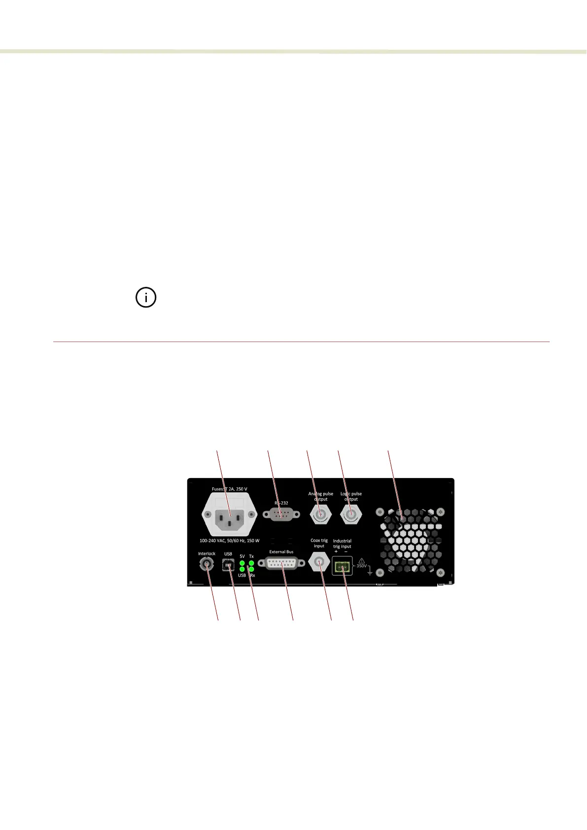
Rear panel interfaces
The rear panel includes electrical ports, status LEDs, and the laser’s exhaust vent.
The panel and its components are depicted in Figure 6.
Figure 6 Rear panel features and connectors
1 AC input – IEC C14 7 USB serial port – type B USB
2 RS-232 serial port – 9 pin female D-sub 8 USB port Status LEDs
3 Analog pulse output – BNC 9 External bus – 15 pin female D-sub
4 Logic pulse output – BNC 10 Coax trig input – BNC
5 Exhaust vent – cooling fan 11
Industrial trig input – 2 pin 5.08 mm
i
i. 5.8 mm pitch pluggable terminal block
6
Interlock connector – LEMO 2-pin
ii
ii. See Connecting the safety interlock on page 75
5
3
1
2
4
8 9
11
106 7