79
Connecting the optical output
Collimator
installation
The collimator
1
is constructed so that its sleeve is inserted into a holder
2
or a
receptacle of a next stage optical device such as a SuperK accessory. To install
the collimator, follow the instructions in Procedure 9.
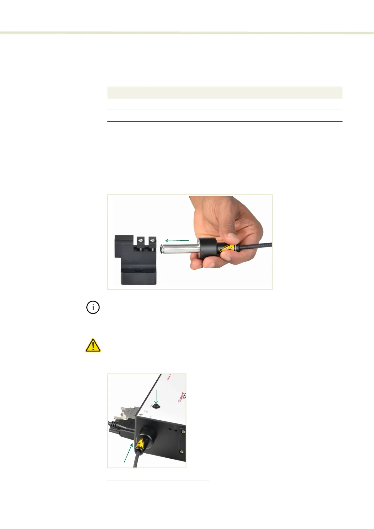
Procedure 9 Installing the Collimator
Figure 47 Inserting the Collimator into a Holder
1
Note: Use of non-NKTP holders: we recommend to gently fix the collimator output
barrel using plastic screws instead of metal screws thereby minimizing the risk of
scratching the collimator.
Caution: Scratching the collimator may prevent it from fitting into the collimator in-
put receptacle of SuperK accessories.
Figure 48 Collimator Installed into a SuperK Accessory Receptacle
1. Model# S024-010-020 only
2. SuperK collimator holder A000-000-002
Action
1 Remove the yellow protective cap from the end of the collimator sleeve.
2 Carefully align the collimator sleeve with the target receptacle as shown in Figure 47.
3 Slide the collimator into the receptacle and then:
• for SuperK accessories: push down on the release button and insert the
collimator into the receptacle until it stops as shown in Figure 48. Then release the
button to lock the collimator in place.
• for holders, power meters etc.: slide the sleeve into the receptacle until it stops.
Then tighten the mounting screws to securely retain the collimator as shown in
Figure 49.