75
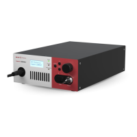
6 Connecting the Laser
Before operating the laser, follow the procedures in this chapter to ensure its
correct and safe operation.
For information on how to connect:
• the Safety Interlock – see “Connecting the safety interlock” on page 75
• Power – see “Connecting power” on page 77
• The Optical Output – see “Connecting the optical output” on page 78
• Accessories – see “Connecting accessories with the external bus” on
page 80
• Trigger input ports – see “Trigger input ports” on page 82
• Synchronization output ports – see “Synchronization output ports” on
page 83
Connecting the safety interlock
To comply with safety regulations and help provide a safe operating
environment, the safety interlock of the laser must be connected to a switch
activated by an access door to the laser’s enclosure. When the connected switch
is opened by the door, it opens the interlock circuit which turns off laser
emission. To prevent the laser immediately turning on when the door
subsequently closes, the key lock must first be cycled (ON–OFF–ON). This resets
the interlock relay to allow emission.
Interlock operation The interlock circuit in simple terms is a closed loop. When the loop is broken,
the laser control circuitry detects this and sends a shutdown signal to the laser.
The loop can be broken by either the key switch relay, the door switch, or the
External Bus loop. In Figure 45, the key switch is turned to the ON position which
the logic circuit detects and in turn energizes the key relay. Since the door switch
is closed, and the external bus circuit is looped with the bus defeater, the laser
control circuitry will permit laser emission.