85
Synchronization output ports
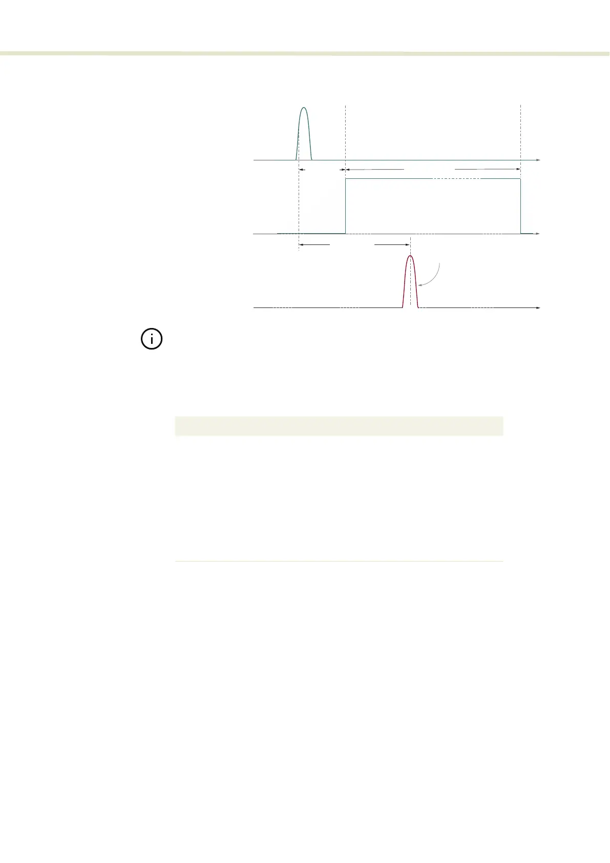
Figure 55 Logic pulse output vs. Analog pulse output
Note: As mentioned for the Analog pulse output, the actual total advance can vary
and is dependent on the final application setup, where the length of the trigger ca-
bles versus the actual total optical path length can shorten or lengthen the ad-
vance time.
Table 13 Logic pulse output
time
Optical ouput
time
Analog pulse output
12 ns ± 1 ns
1.8 µs ± 0.2 µs
45-55 ns ±2 ns
High
Low
Parameter Value
Input impedance
50 Ω[
Nominal pulse voltage
i
i. 50 Ω load
2.5 V
Minimum pulse width
1 µs
Nominal Low-level output voltage
0 V
Connector type
BNC
Cable type
ii
ii. Recommended
Use RG223 type or similar double
shielded cable 3M