Connecting the optical output
78
Procedure 8 Connecting power
Connecting the optical output
Warning: Care should be taken to mount the collimator so that the beam emitted
is contained in an area where no personnel or flammable material is present.
Back reflection When building and connecting your optical system, you must be careful to avoid
creating a path where Back Reflection (BR) can occur. BR occurs when a laser
beam is reflected back into the laser cavity. This increases noise and may cause
the laser beam to scatter causing damage or injury.
You must always reduce the risk of BR into the laser. For example, in a bulk-optic
system, ensure all reflective optics are securely fixed, minimizing the risk of back-
reflected light into the laser. Also, before turning on the laser the first time, check
the optical path to confirm no BR is possible from the application light path.
Warning: Back reflection (BR) is a hazard and may cause injury or damage.
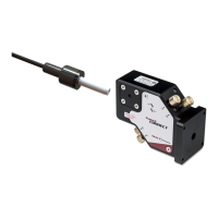
FC connector
installation
When a SuperK FC connecterized fiber
1
is mated to another connecterized
component, there is a risk of damage to the connector. Any loss, dirt or stress at
the connector mating junction, can result in damage due to the significant peak
power capability of the laser.
When connectors are mated, it is not guaranteed that this damage can be
avoided. You can reduce the risk by ensuring the fiber facet is clean as described
in the following.
Cleaning the fiber facet
Before connecting the output, ensure that the fiber facet is clean and free of dust
particles. A fiber facet fouled by foreign particles, oil, or other contaminants may
cause severe damage to the fiber facet resulting in a significantly distorted beam
profile. Dust from the fiber facet may be removed using a number of approved
fiber cleaning methods. Lens cleaning tissue (lint free wipes) or similar
appropriate material may be employed. See “Fiber Maintenance” on page 97 for
further information on preparing the fiber surface for mating.
Note: The exit delivery fiber and connector are NOT covered by the laser’s
warranty.
Action
1 Connect the AC cable supplied with the laser to the rear 3-pin IEC power input connector.
2 Connect the AC cable to a local AC mains supply.
3 Press the power toggle button to the ON position. (The switch is next to the keyswitch on
the front panel.)
1. Model#s S024-010-000 and S024-010-010 only