Connecting the safety interlock
76
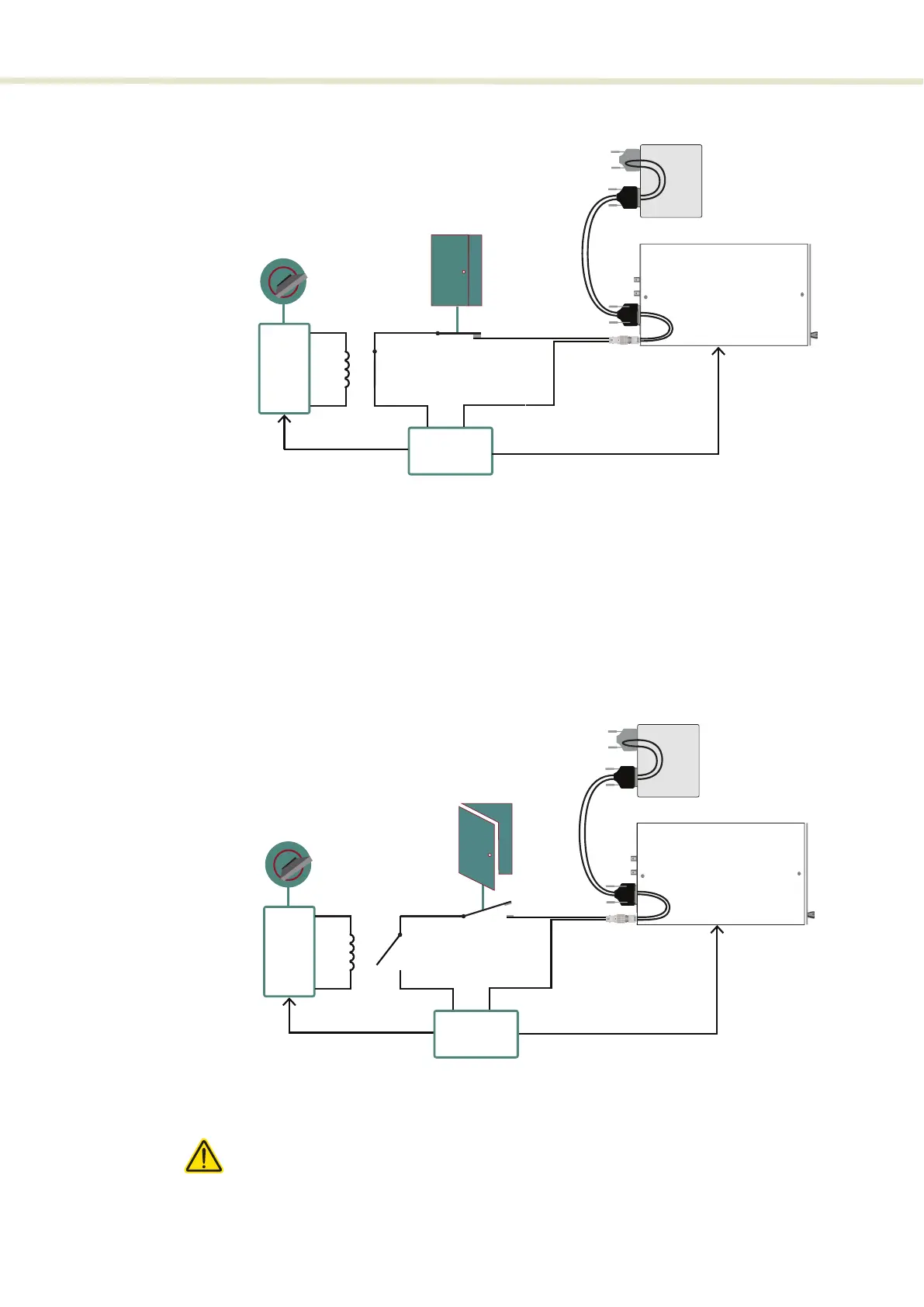
Figure 45 Interlock connected to a door switch - Laser ON
Figure 46 shows the interlock loop broken by the door switch opening. The
control circuitry detects this and immediately sends a shut down signal to the
laser (the laser pump). In addition, the control circuitry sends a reset to the key
switch logic circuit. The reset will cause the logic circuit to de-energize the
Normally Open relay in the interlock circuit. The only way to close the relay again
is to cycle the key to OFF and then ON. This sets the logic circuit (a D Flip-Flop) to
energize the coil again closing the relay.
Figure 46 Interlock connected to a door switch - Laser SHUTDOWN
Caution: Do not short-circuit the Interlock input. Short-circuiting the interlock cir-
cumvents safety regulations and NKT Photonics does not take liability for any in-
juries or damage caused by doing so.
O
On
Logic Circuit
Laser Control Circuitry
Reset
Set
Normally
Open
Door
Switch
SuperK EVOSuperK EVO
Energized
Interlock
Monitor
Interlock
Connector
Bus Defeater
Accessory
Shutdown Laser
SuperK COMPACT
(Bottom view)
External
Bus
Cable
O
On
Logic Circuit
Laser Control Circuitry
Reset
Set
Shutdown Laser
Normally
Open
Door
Switch
Interlock
Monitor
De-energized
Interlock
Connector
External
Bus
Cable
Bus Defeater
Accessory
SuperK COMPACT
(Bottom view)
2