8.5.3 Writing program Nos. 1 - 8
Writing to program Nos. 1-8 is explained below.
The contents of program Nos. 1-8 are retained even when power failure has occurred and when the
PLC has been reset.
Setting the limit switch output data to program Nos. 1-8 is carried out in PRGM mode.
Setting sequence is as below.
(1) Turn the PLC Ready signal OFF(command 1: 7 bit).
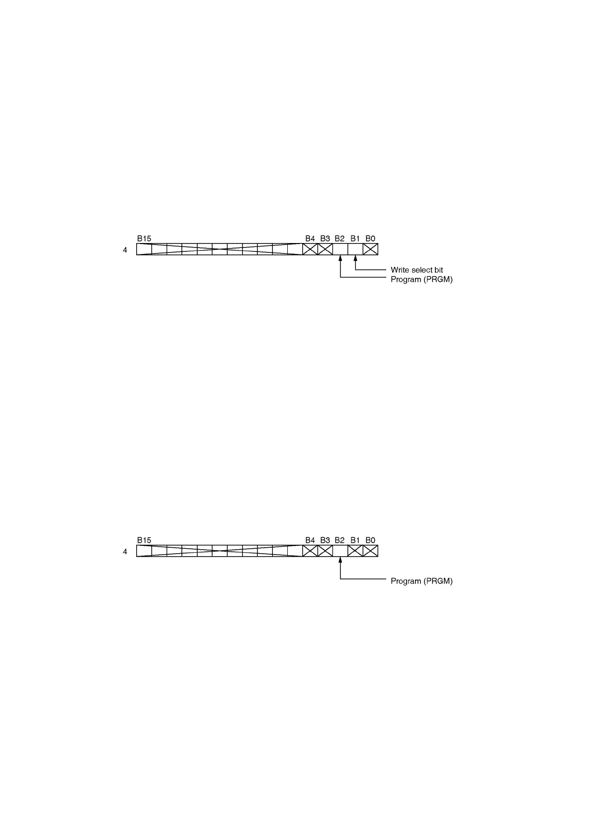
(2) Set ‘1’ to the program (PRGM) bit and the write select bit of buffer memory sequence mode
selection. Set ‘0’ to other bits.
When using the external setting unit (VS-T62 or VS-T62B), set manual mode to RUN.
(3) Write the program No. to the buffer memory program No. setting area.
(4) Turn the PLC Ready signal ON.
(5) Writing is completed when the operation status (status 1: 7 bit) has turned ON.
8.5.4 Reading program Nos. 1-8
Reading program Nos. 1-8 is explained below.
Reading the limit switch output data from program Nos. 1-8 is carried out in PRGM mode.
The contents of program Nos. 1-8 are retained even when power failure has occurred and when the
PLC has been reset.
Reading sequence is as below.
(1) Turn the PLC Ready signal OFF (command 1: 7 bit).
(2) Set ‘1’ to the program (PRGM) bit of buffer memory sequence mode selection.
When using the external setting unit (VS-T62 or VS-T62B), set manual mode to RUN.
(3) Write the program No. to be readout to the buffer memory program No. setting area (I/O address
4099 [4163]).
(4) Turned the PLC Ready signal ON.
(5) Reading is completed when the operation status (status 1: 7 bit) has turned ON.
(6) Execute the readout of the limit switch output data from buffer memory.