6.2 Initial Setting
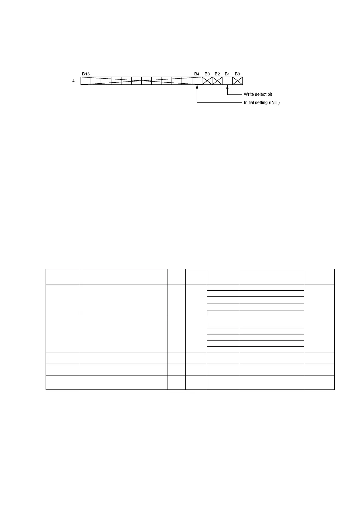
When setting the values in the sequence format, set “1” to the corresponding bit of the buffer memory
(sequence mode selection).
When writing the current position value, set “1” also to “write select” bit. The data written to the buffer
memory for data communication with the PLC CPU is loaded to the VS-212DN when the PLC Ready
signal is turned ON in sequence mode.
[Setting sequence]
(1) Turn the PLC Ready signal (command 1: 7bit) OFF
(2) Set “1” to initial setting (INIT) of sequence mode selection (I/O address: 4).
(3) Write the setting value to buffer memory addresses 16392 to 16395 (For axis 2: 16456 to 16458).
(4) Turn the PLC CPU signal (PLC Ready signal) ON.
(5) Writing is completed when operation status (status 1: 7 bit) has turned ON.
Note:
Current position settings are executed simultaneously for 2 axes. To designate settings at each axis
individually, use the current position preset function.
Important:
Writing to initial setting/parameter setting areas shall not exceed 10,000 times.
6.3 Initial Setting List
I/O
Address
Name
Data
format
Initial
value
Data range Description
Parameter
No.
16392
(16456)
Sensor type and
rotational direction
USINT
0
90
_
_
16393
(16457)
Decimal point position USINT
0
91
Scale length UDINT
131072
92
Minimum current position value DINT 0
93
16396
(16460)
Current position value DINT 65536
-99999~
999999
94
* ( ): Address for axis 2
Note: The decimal point should be omitted when designating the scale length, minimum current
position value, and current position value settings.