7.1.4 Control timing
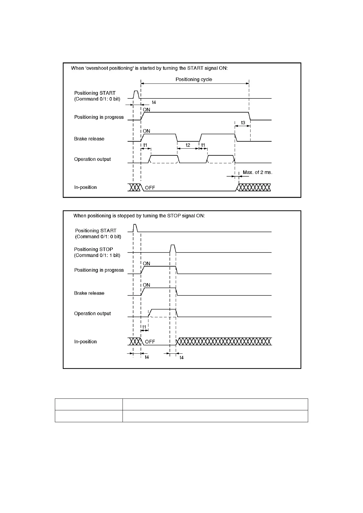
The following charts show the ON/OFF timing for each of the positioning control signals.
(1) The ‘operation output’ item shown above consists of the following outputs:
Speed switching format FWD, RVS, High-speed, Low-speed
Speed stepping format FWD Low-speed, RVS Low-speed, High-speed, Medium-speed
(2) ‘t1’ indicates the delay period from the point when the brake is released, until the point when the
operation output comes ON. (10 ms)