3.5.12 Target Stop Position Writing
This function writes the target position which is required for positioning operations. Although target
positions can be written by the sequence program at all times, that data is only enabled when an online
positioning start occurs.
(1) Data is written in a scaling binary format.
(2) The permissible setting range is as follows:
[Min. current position value] to [Min. current position value + scale length - 1].
(3) Error 41 occurs at positioning starts if the target position is outside the detectable range, or if it is
within the detectable range, but the motion momentarily violates the detectable range when
positioning is started from an overshoot point or within the stop zone.
(4) The default setting of "0" is established at power on.
3.5.13 Forward/Reverse Stop Zone After Learning Function (Reading)
The learning function permits stop zone corrections to be read. If the learning function is disabled, the
stop zone which was used for positioning is read. There are two data items; one for Forward rotation,
and one for Reverse rotation.
3.5.14 Speed Limit Writing
This setting limits the positioning speed. Although the speed limit can be written by the sequence
program at all times, it is only enabled when an online positioning start occurs. The default setting of
"3" (no speed limit) is established at power on.
Positioning at low-speed only
Positioning at low-speed only
No speed limit
A setting other than 1 to 3 results in an error. A speed limit setting cannot be specified for JOG
operations.
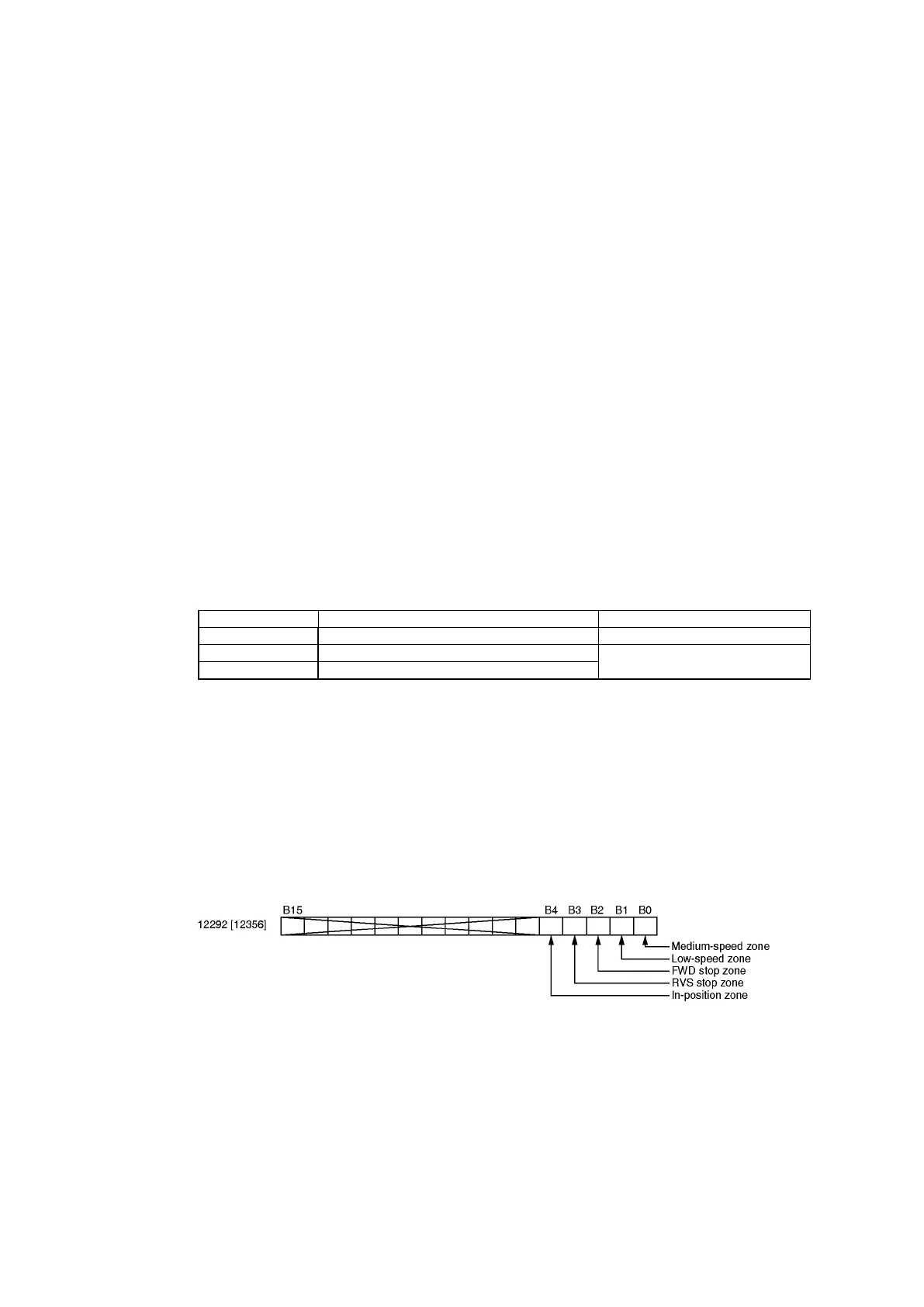
3.5.15 Buffer Memory Selection For Positioning Pattern Data (Writing)
The pattern data used in positioning operations can be selected from the "buffer memory" and
"parameter data". Pattern data which is to use the buffer memory can be specified by specifying a
setting of "1" for the bit which corresponds to that pattern data. All other bits are set to "0".
At power on, the default setting of "0" is established for all bits.
3.5.16 Medium-Speed Zone Writing
This setting specifies the medium-speed zone for speed stepping positioning operations. Although this
setting can be written by the sequence program at any time, it is enabled only when the positioning
pattern data buffer memory selection's (I/O address 12292 [12356]) 0-bit is set to "1".
This setting value changes to the parameter setting data at power on, and when parameter settings are
made.
(1) Setting data is written in a scaling binary format.
(2) The permissible setting range is as follows:
[Min. current position value] to [Min. current position value + scale length - 1].