EasyManuals Logo

NSD Varlimit VS-212DN User Manual

Default Icon
144 pages
To Next Page IconTo Next Page
To Previous Page IconTo Previous Page
Page #54 background imageLoading...
Page #54 background image
6-4
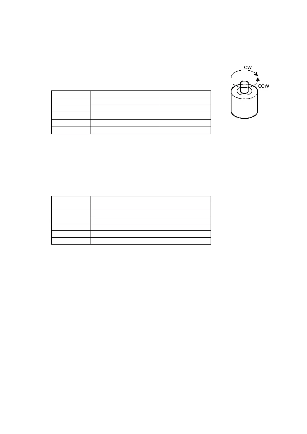
6.3.1 Sensor selection/sensor rotation direction setting (I/O address: 16392 [16456])
The direction of rotation in which the position data value increases are designated as either CWor
CCW(viewed from sensor shaft direction) and sensor type.
(1) CW direction
In this direction, the current position value increases.
(2) CCW direction
In this direction, the current position value increases.
Setting data
Sensor type
Rotation direction
0
MRE-32SP062
CW
1
MRE-32SP062
CCW
2
MRE-G[ ]SP062
CW
3
MRE-G[ ]SP062
CCW
99
No sensor
6.3.2 Decimal point position setting (I/O address: 16393 [16457])
The decimal point position is set for the display area of the external setting unit (VS-T62 or
VS-T62B). This setting does not affect the binary data used for the PLC. The decimal point
position is determined by the number of digits after the decimal point.
Setting data
Decimal point position
0
0
1
0.0
2
0.00
3
0.000
4
0.0000
5
0.00000

Table of Contents

Questions and Answers:

Question and Answer IconNeed help?

Do you have a question about the NSD Varlimit VS-212DN and is the answer not in the manual?

NSD Varlimit VS-212DN Specifications

General IconGeneral
BrandNSD
ModelVarlimit VS-212DN
CategoryController
LanguageEnglish