3.5.1 Manual Mode Input/Output Status Reading
The following status are read.
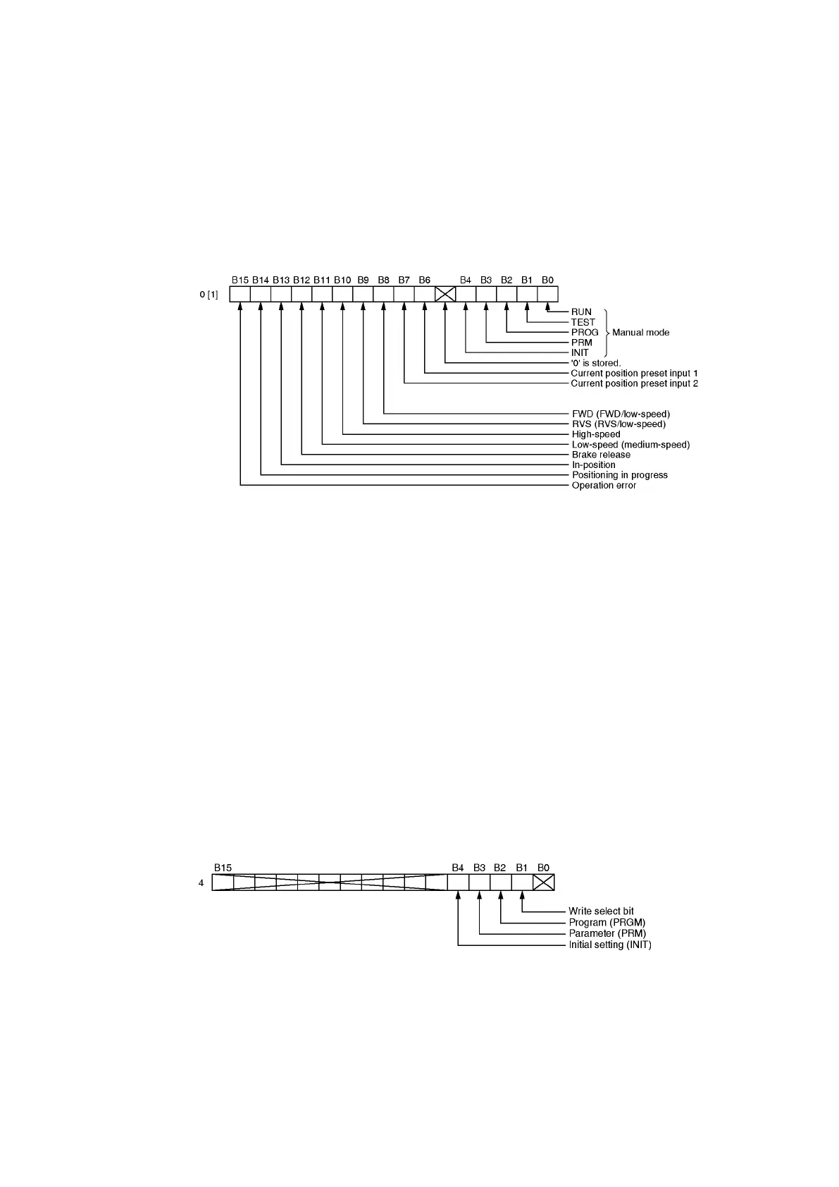
(1) Manual mode using the VS-T62 or VS-T62B
The bit which corresponds to the selected manual mode (specified from the external setting
unit VS-T62 or VS-T62B) is set to "1". If the external setting unit is not being used, "B0"
becomes "1".
(2) Current position preset input status
Becomes "1" when the relevant current position preset input switches on.
(3) Output status
Becomes "1" when the relevant output switches on.
3.5.2 Error Code Reading
Error codes are read when errors occur. Error codes can be cleared by the following operations.
(1) Turn the "error reset" (command 1: 6 bit) command on from the sequence data.
(2) Turn the power off.
(3) Press the [CLR] key at the external setting unit (VS-T62 or VS-T62B).
(4) Change the Manual mode's mode (mode selected from external setting device).
(5) Change the Sequence mode's mode (mode selected from PLC).
3.5.3 Function Selection (Parameter Writing)
VS-212DN offers the following settings: "0" (joint usage for positioning), "1"(limit switch output only),
and "2" (current position detection only). However, only the "0" setting should be selected (this is the
default setting). Operation cannot be guaranteed if any setting other than "0" is selected.
3.5.4 Sequence Mode Selection Writing
This is the area where the appropriate mode for data writing conditions is selected when writing the
parameter data and the limit switch output ON/OFF data from the PLC CPU. This mode is selected by
the PLC CPU. Therefore, this is called 'sequence mode' to distinguish it from the mode (manual
mode) selected by the VS-T62 or VS-T62B.
Set '1' to the bit corresponding to the desired sequence mode when RUN or TEST in manual mode is
selected. Set '0' to other bits. Setting '1' to both bits will cause an error. The data written to the
buffer memory for data communication with the PC CPU is loaded to the VS-212DN when the PLC
Ready signal (command 1: 7 bit) is turned ON in sequence mode.
Even when sequence mode is selected, if manual mode is changed o anything other than RUN or
TEST, priority is given to manual mode.
(a) Current position is set by INIT in sequence mode.
(b) Program is written by PRGM in sequence mode
Set '1' when writing in the above cases. Become “0” as a default value when power ON.