3.3.2 IN Data Format (Produced Connection)
IN data occupies 8 bits. The status and data are determined by the command and data bit content.
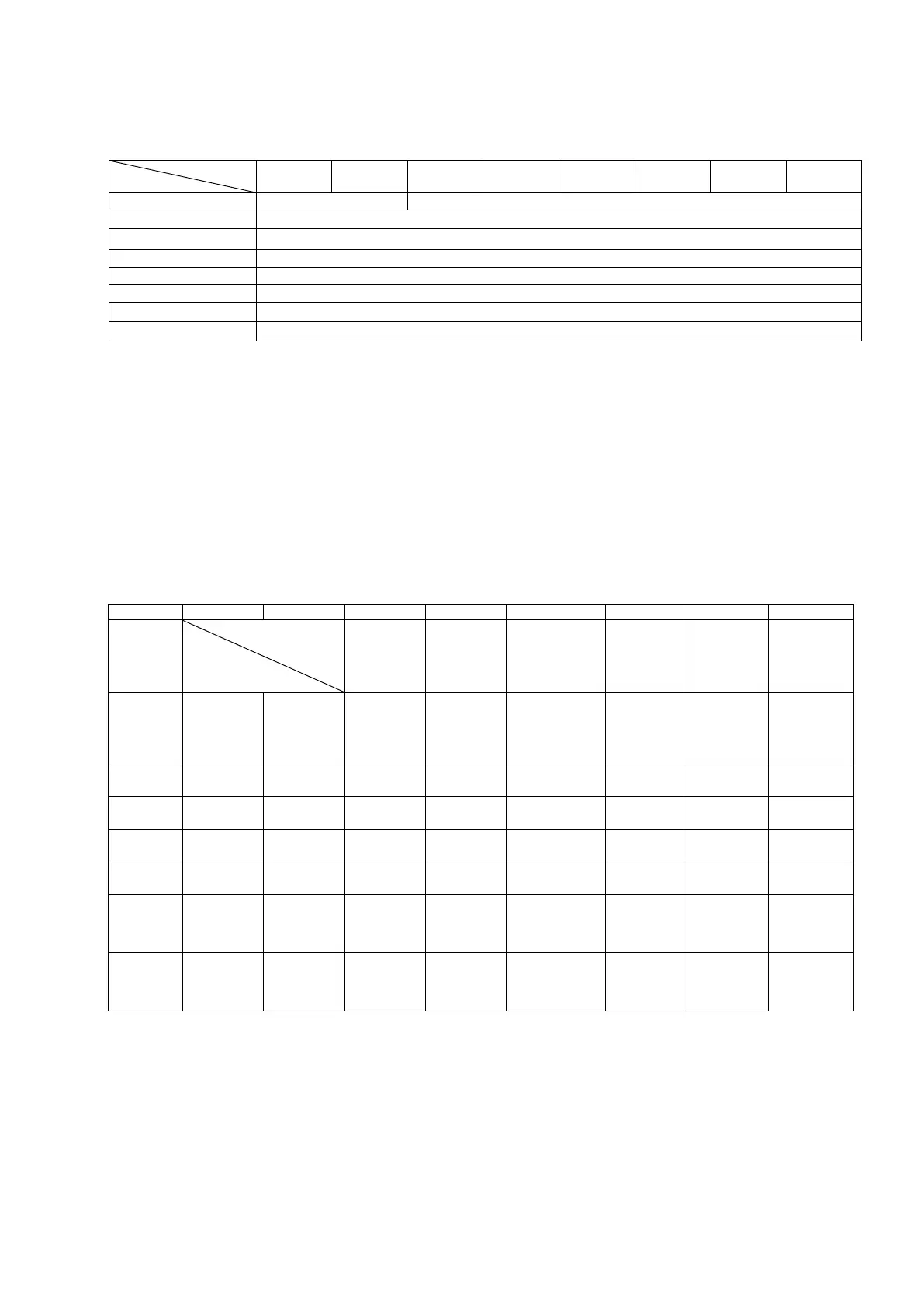
7 6 5 4 3 2 1 0
Status 2 / I/O Address (LSB)
Status 3 / I/O Address (MSB)
Status 7 / Data 3 (MSB) / Error code
Reply bits
00: Indicates a 0 to 7 status (error) at the VS-212DN. Indicates an "end in error" condition during data
reading/writing, and the error code is written to address 7.
01: Indicates an error-free completion of data reading.
10: Indicates an error-free completion of data writing.
11: Indicates an error-free completion of the command simultaneously with data writing.
(1) Status bits
Status bits are enabled when the reply bit (see above) is "00", "10", or "11", and the VS-212DN writes
the following signals to the PLC.
However, when the command bit is "01", "10", or "11", and the reply bit is "00", this indicates that data
reading/writing ended in error, and the error code is written to address 7.
Status 0
Axis 1
error
Excessive
current
position
Axis 1
Excessive
correction
amount error
Axis 1
Sensor error
Axis 1
Lower limit
overtravel
Axis 1
Upper limit
overtravel
Status1
VS-212DN
Operation
status
“0” fixed
Axis 2
error
Excessive
current
position
Axis 2
Excessive
correction
amount error
Axis 2
Sensor error
Axis 2
Lower limit
overtravel
Axis 2
Upper limit
overtravel
Status 2
Status 3
Status 4
Status 5
Status 6
Axis 1
Operation
error
Axis 1
progress
Axis 1
In-position
Axis 1
Brake
release
Axis 1
Low-speed/
medium-speed
Axis 1
High-speed
Reverse/
Reverse
Forward/
Forward
Status 7
Axis 2
Operation
error
Axis 2
progress
Axis 2
In-position
Axis 2
Brake
release
Axis 2
Low-speed/
medium-speed
Axis 2
High-speed
Reverse/
Reverse
Forward/
Forward
(2) Data reading request (command/data: 01)
When the reply bit is "01", the I/O address (Hex, Word) is enabled at addresses 2 and 3, and the I/O
address data is enabled at addresses 4 to 7.
(3) Data writing request (command/data: 10, 11)
When the reply bit is "10" or "11", an "error-free completion of data writing" status is enabled.