3. DeviceNet
VS-212DN operates as a "group 2 only" slave module for FA field networks. Therefore, VS-212DN requires
a master module for communication with the PLC DeviceNet. Using such a DeviceNet communication
module enables the PLC to control VS-212DN as a regular I/O unit.
For details regarding operation of the DeviceNet communication module and the DeviceNet communication
setting procedures, refer to the manufacturer's manual.
It is also possible to use DeviceNet devices available from PLC manufacturers, etc., to enable reading
and writing in the VS-212DN buffer memory. Contact NSD if a file (EDS file) is required which defines
the control data used by the DeviceNet devices.
3.1 Control Panel Settings
The VS-212DN control panel is equipped with switches for node address and baud rate setting.
(1) Specify a node address setting of 0 to 63. Be sure that duplicate node addresses (same as address for
another module) are not specified.
[Ex] If node address = 5: Set 1 (SW6) and 4 (SW4) to ON.
(2) Baud rate setting
500kbps ON OFF
250kbps OFF ON
*Note ON ON
*Note: This combination is prohibited.
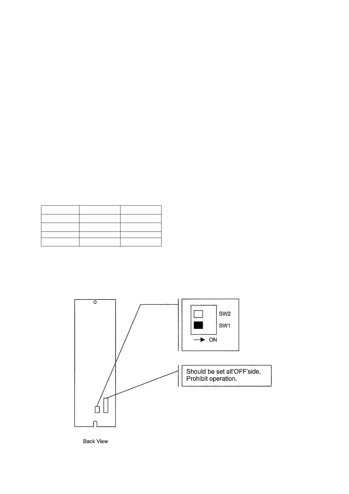
(3) PLC selection switch (SW 1) setting
When Rockwell Automation’s master unit is connected to the VS-212DN unit, SW 1 on the VS-212DN
rear panel should be set to ‘ON’ side.