3.3 Interface
I/O data is used for data updates with the PLC master unit. Reading and writing of the VS-212DN control
data (buffer memory) is also possible in addition to the usual command and status updates (I/O bits).
(Writing requires that certain conditions be satisfied.)
Unless otherwise indicated in this manual, IN/OUT expressions are used as viewed from the PLC. For
example, the OUT data shown below is data which is written from the PLC.
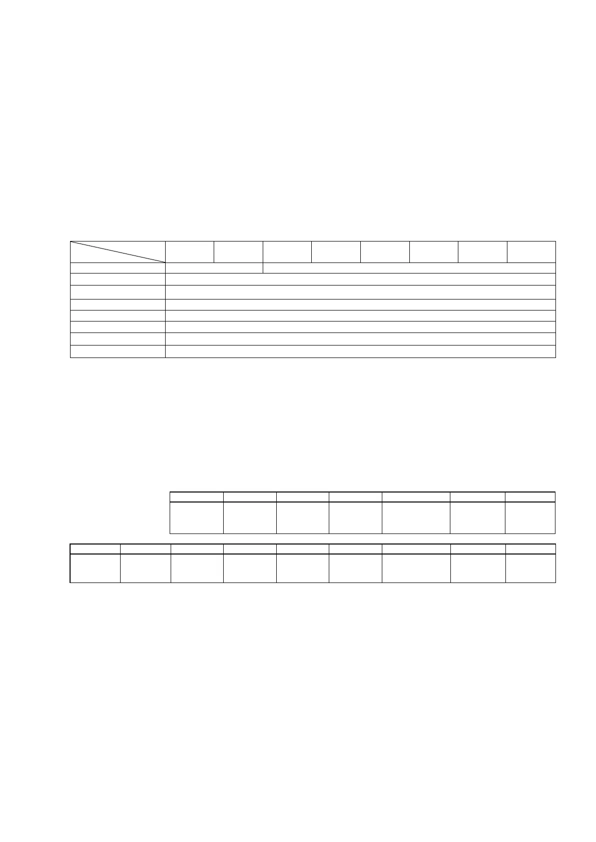
3.3.1 OUT Data Format (Consumed Connection)
OUT data occupies 8 bits. The command and data are enabled/disabled according to the command/data
bit content shown below.
7 6 5 4 3 2 1 0
2 I/O Address (LSB)
*Command/Data bits
00: Only the command bit is enabled.
01: Only the data reading request is enabled, and the command bit is disabled.
10: Only the data writing request is enabled, and the command bit is disabled.
11: Both the data writing request and the command bit are enabled.
(1) Command bit
When the command/data bit is "00" or "11", the command bit is enabled, and the VS-212DN
receives the following signals from the PLC.
Command 1 PLC ready
Error
cancel
output
Reverse
Forward
Current position
Axis 2
Stop
Axis 2
Start
*Each bit, 1: enabled, 0 disabled
(2) Data reading request
When the command/data bit is "01", I/O address data reading can be performed by writing the I/O
address (Hex, Word) to addresses 2 and 3.
(3) Data writing request
When the command/data bit is "10" or "11", I/O address data can be changed by writing the I/O
address (Hex, Word) to addresses 2 and 3, and writing the data to addresses 4 to 7.
Data is written from the LSB side in accordance with the data size.
Command 0 Mode Lock
Axis 1
Reverse
JOG
Axis 1
Forward
JOG
Axis 1
Current position
preset command
Axis 1
Stop
Axis 1
Start