8.2 Initial Settings
Refer to section 6.2 and 6.3 for the VS-212DN’s initial settings.
The initial setting are commonly used for the current position detection function, limit switch output
function, and positioning function.
8.3 Parameter Settings
This section explains the parameter settings for the VS-212DN’s limit switch output.
When writing the parameters, set ‘1’ to the corresponding bit of the buffer memory address (sequence
mode selection). Set ‘0’ to other bits.
The data written to the buffer memory for data communication with the PLC CPU is loaded to the
VS-212DN when the PLC ready signal is turned ON in sequence mode.
Note:
Some parameters of the VS-212DN are for the positioning function and current position detection.
Setting sequence:
(a) Turn the PLC Ready signal (command 1: 7 bit) OFF.
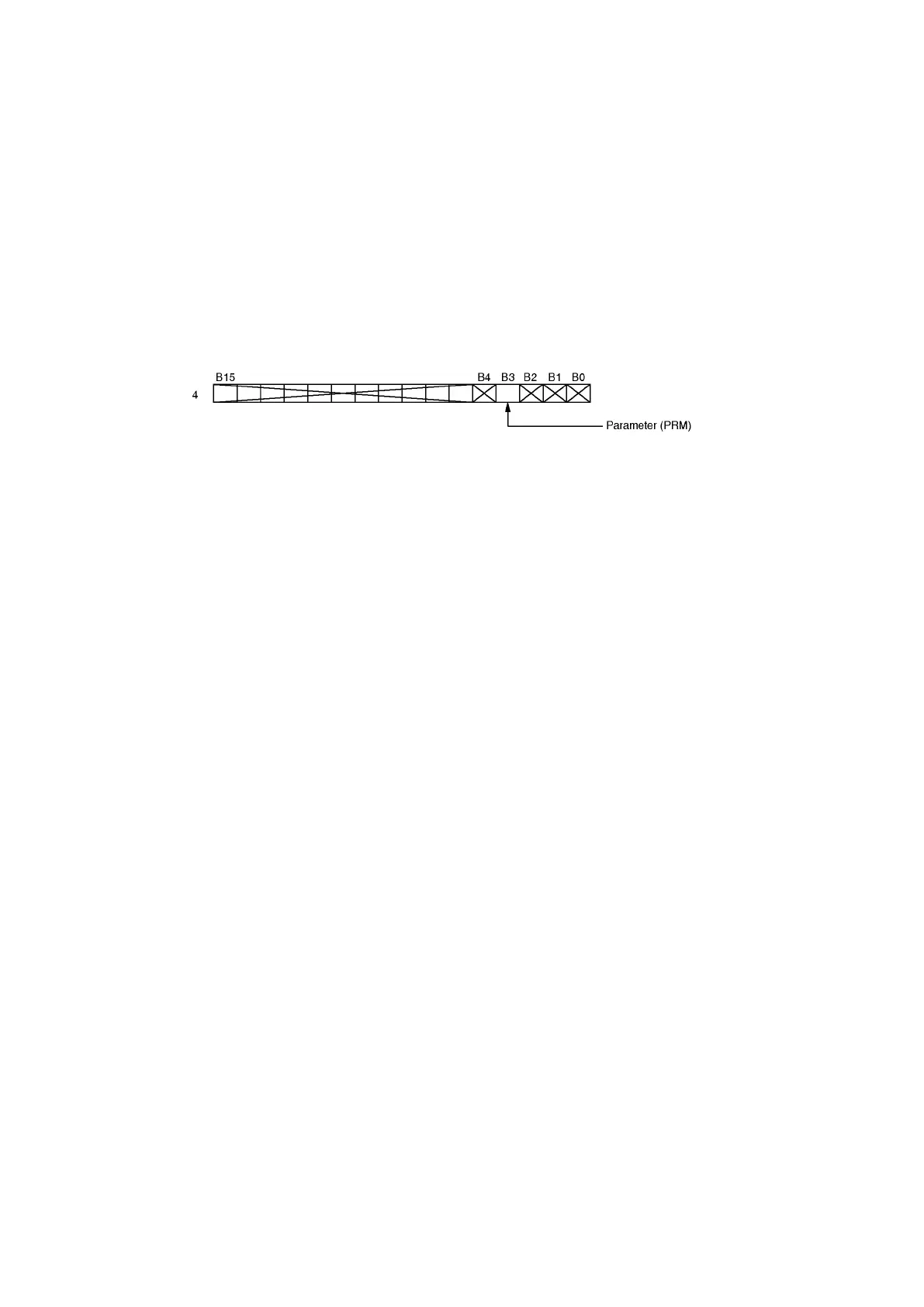
(b) Set ‘1’ to parameter (PRM) of buffer memory address for sequence mode selection (I/O address: 4).
(c) Write the setting value to buffer memory I/O addresses 4100 to 4102 (4164 to 4166).
(d) Turn the PLC Ready signal ON.
(e) Writing is completed when operation status (status 1: 7 bit) has turned ON.
Important:
Writing to initial setting/parameter setting areas shall not exceed 10000 times.