(1) The positioning operation is controlled by the following 8 output signals:
These four outputs (a to d) are called ‘operation output’)
a. FWD (forward/low-speed for ‘speed stepping format’)
b. RVS (reverse/low-speed for ‘speed stepping format’)
c. High-speed
d. Low-speed (medium-speed for ‘speed stepping format’)
e. Brake release
f. In-position
g. Positioning in progress
h. Operation error
(2) A single VS-212DN can execute positioning control for 2 axes.
(3) The limit switch output function can be used while using the positioning function.
(4) The positioning function is started when the VS-212DN’s start signal (command 0/1: 0 bit) is turned ON.
(5) A target stop position setting can be written to the buffer memory while the VS-212DN positioning
operation is in progress.
Positioning begins when the start signal (command 0/1: 0 bit) is turned ON; the target stop position
setting read at that time, a subsequent changes made in the target stop position setting will not
affect the positioning operation already in progress.
(6) The setting range for the target stop position is according to the ‘scale length’ and ‘minimum current
position value’ as follows:
Target stop position setting range = [Minimum current position value] to [minimum current position
value + scale length – 1]
Even if the target stop position is within the permissible setting range, error 41 will occur under the
following conditions
a. When the position after a positioning overshoot is outside the permissible setting range.
b. When a positioning START occurs within the stop zone, and a position equivalent to the ‘length
of the stop zone multiplied by 2’ is outside the permissible setting range.
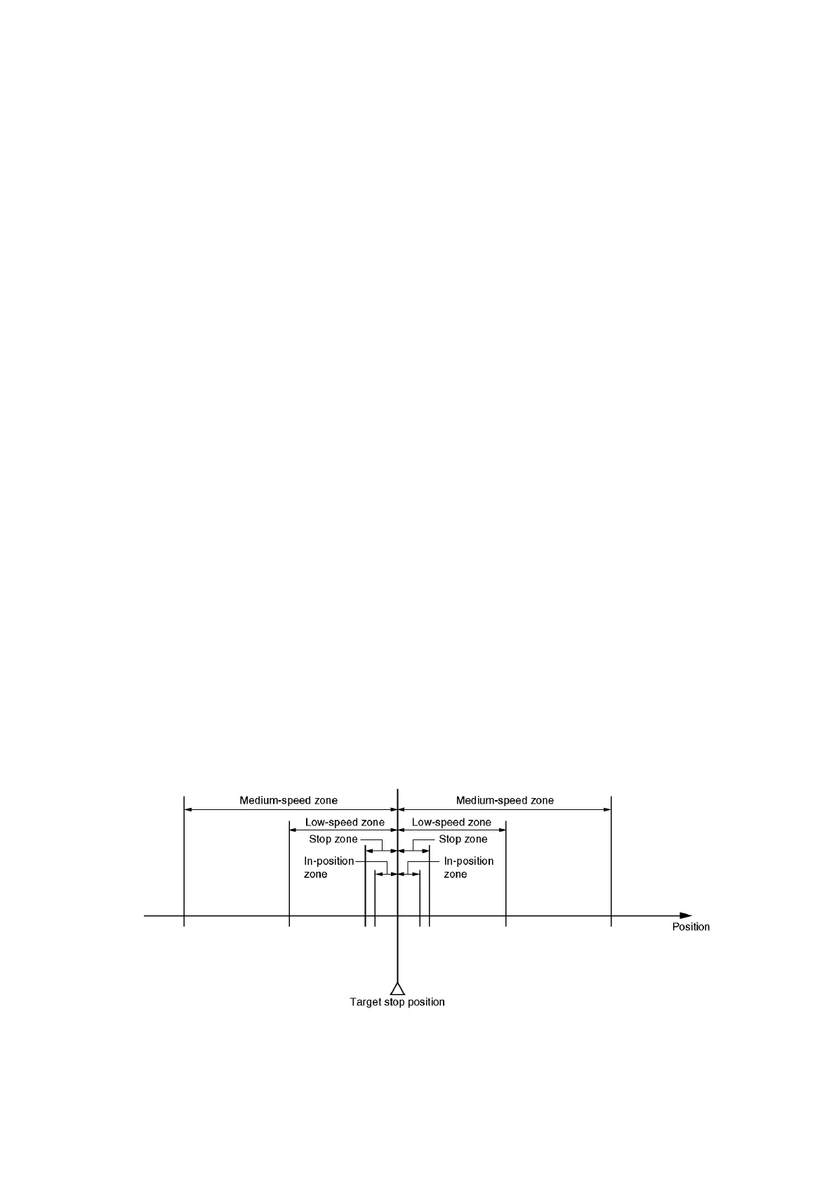
(7) The medium speed zone, low-speed zone, stop zone, and In-position zone are shown below
relative to the target stop position.
Although the brake is applied at the stop zone position, subsequent motion due to inertia should be
considered when designating the stop zone setting in order to ensure that motion is stopped at the
target position.