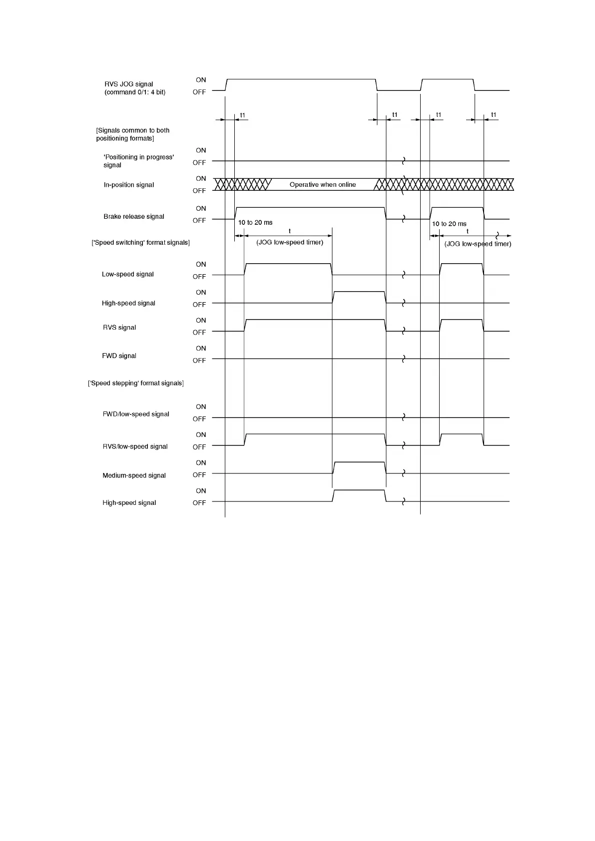
(2) The timing chart for the ‘RVS JOG’ operation is shown below.
(3) If the JOG signal is ON when the ‘JOG low-speed timer’ period (‘t’ at item (1) and (2) timing charts
above) has elapsed, an automatic low-speed to high-speed switch will occur.
The ‘JOG low-speed timer’ value period is designated by parameter. Even if a ‘t = 0.00’ setting is
designated, a low-speed output of up to 10 ms may occur.
(4) The positioning START signal (command 0/1: 0 bit) will be inoperative during a JOG operation.
(5) A ‘RVS JOG’ signal input (command 0/1: 4 bit) will be inoperative during ‘FWD JOG’ (command 0/1:
3 bit) operation, and vice verse.
(6) If both the ‘FWD JOG’ (command 0/1: 3 bit) and ‘RVS JOG’ (command 0/1: 4 bit) signals are turned
ON simultaneously, the ‘FWD JOG’ signal will have priority.
(7) Even if a simultaneous direction switch is designated for the JOG operation, the VS-212DN will
automatically add a STOP period of 50 ms.
(8) ‘t1’ is the period which elapses between PLC I/O writing, and the start of VS-212DN operation.
This time period will be 20ms or longer under the following conditions.
o PLC scan time: 4ms.
o DeviceNet: 500kbps
o Slave connection unit: VS-212DN (1 unit)