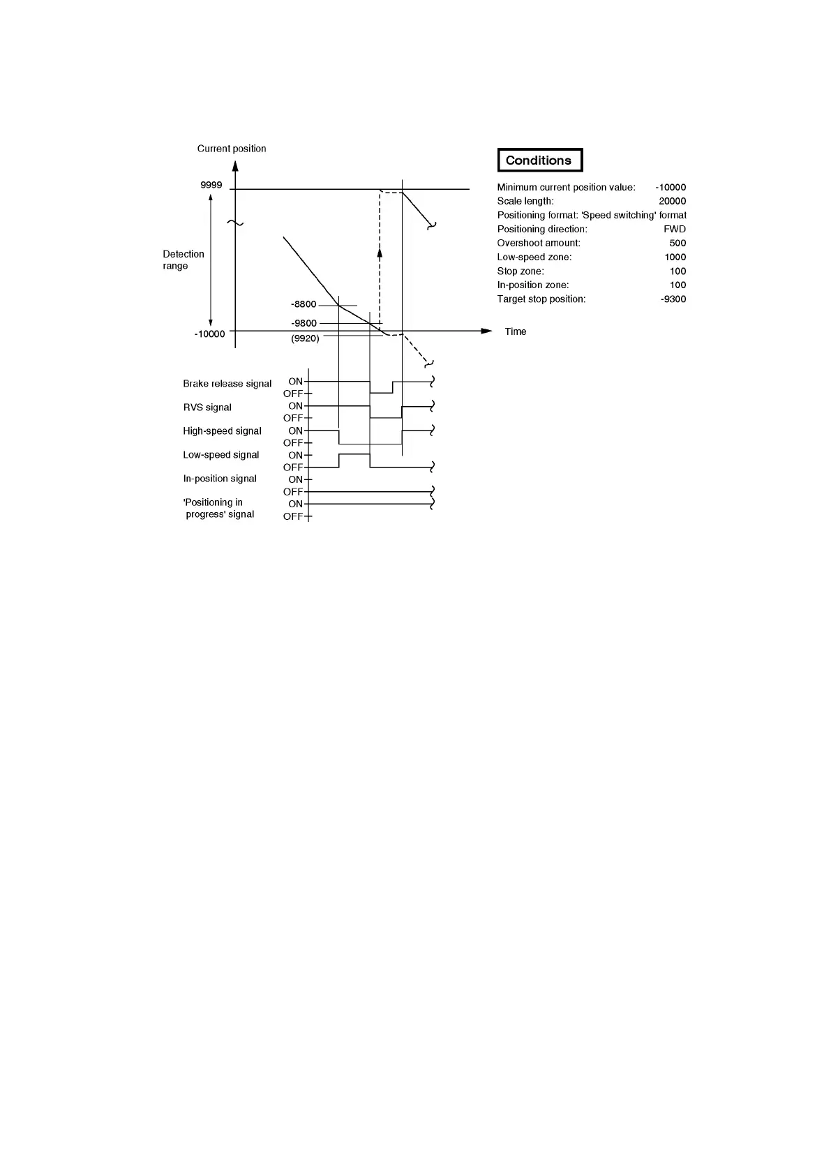
(2) The following example shows a case in which the overshoot point is designated near the minimum
current position value point, resulting in an ‘overshoot stop’ position which is outside the detection
range.
The target position of -9300 becomes -9800 when overshoot occurs, due to an overshoot amount
of 500.
In the above example, the overshoot point of -9800 is overshot in the reverse direction by the
amount of 280 before a stop occurs.
As a result, the detection range limit of -10000 is exceeded, and the current position at the ‘stop
detection’ point will be 9920. At that time, overshoot positioning is automatically re-started toward
the -9300 target position. Use caution regarding the above type of setting, as it could create a
considerable risk depending on the machine being used.
(3) The VS-212DN ‘excessive current position change’ error detection function can be used to detect
detection range violations.
To do this the ‘permissible current position change amount’ setting should be designated according
to the machine being controlled, allowing a slight margin in the travel amount per each 20 ms.
The ‘upper limit/lower limit’ detection function can also be used to detect detection range violations.
In this case, an error will be detected when the prescribed range is exceeded, and operation will be
stopped.
Regardless of which function is used, a sequence program interlock condition must be established
using the ‘excessive current position change’ (status 0/1: 4 bit), ‘upper-limit over detection’ (status
0/1: 0 bit) and ‘lower-limit over detection’ (status 0/1: 1 bit) signals.
Important
(1) The positioning operation should not be used near the upper and lower limits of the detection range.
(2) When the use of the positioning operation near the upper/lower limit is unavoidable, be sure that a
sequence program interlock condition is established, using the appropriate ‘error detection’ signal.
(3) As a backup safely measure, mechanical limit switches should be installed.