Solver NEXT SPM. Instruction Manual
102
7.2.2.2. Preparation for Measurements
The Semicontact Error Mode is based on the Semicontact Mode, which is described in
detail in i. 7.2.1 “Semicontact Mode” on page 84.
Before the Semicontact Error Mode measurements, prepare for the measurements and
perform measurements of surface topography by the Semicontact Mode.
Measuring in the Semicontact Error Mode is carried out with the universal or scanning
measuring head. When measuring with the universal measuring head, it can be supplied
with any measuring insert except AU020 and AU030. The measuring head is equipped
with the semicontact probe.
After the completion of preliminary measurements of surface topography by the
Semicontact Mode, perform setting of parameters for operating by the Semicontact Error
Mode.
7.2.2.3. Scanning
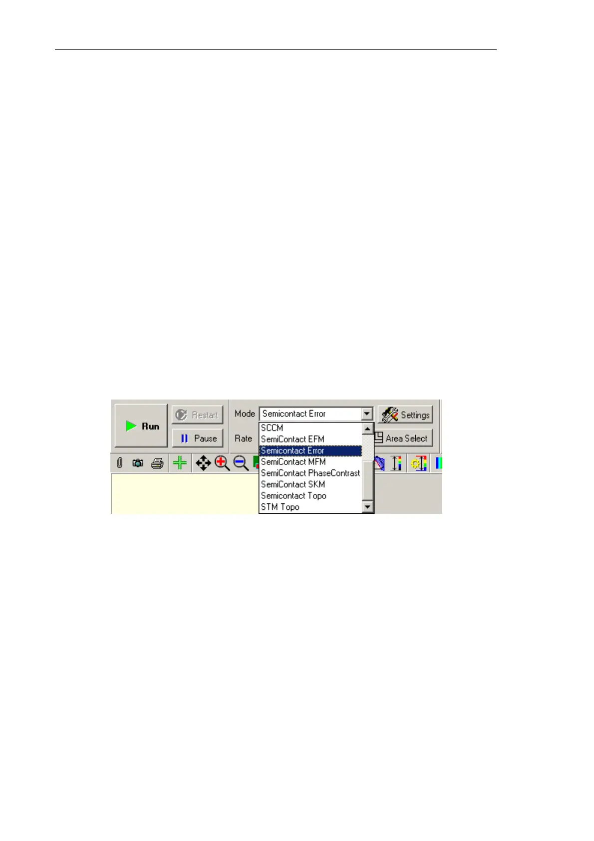
Select the Semicontact Error mode in the Mode list on the Control panel of the scanning
window (Fig. 7-32). For this cofiguration, the Mag signal will be used as the second
detection signal for the first scan pass.
Fig. 7-69. Selecting the
Semicontact Error Mode
Click the button Run, which is on the control panel of the Scan tab, to trigger the process
of scanning.
The following actions take place:
● Line-by-line scanning of the sample surface starts and two images appear in the field of
2D visualization of the scanning data. One of the images is an image of surface
topography (signal
Height), while the other one is the error signal (signal Mag)
(Fig. 7-70);